Linear compressor

A technology of linear compressors and compression mechanisms, applied in mechanical equipment, machines/engines, liquid variable displacement machines, etc., which can solve problems such as collision noise, sudden changes in piston amplitude, and damage to pistons

Inactive Publication Date: 2005-02-23
PANASONIC CORP
View PDF0 Cites 9 Cited by
  • Summary
  • Abstract
  • Description
  • Claims
  • Application Information

AI Technical Summary

Problems solved by technology

[0003] However, since the linear compressor is a free piston reciprocating push type, it is not constrained by other components in the mechanism, so under the action of various external forces such as pressure changes du

Method used


Image

  • Linear compressor
  • Linear compressor
  • Linear compressor

Examples


Embodiment Construction

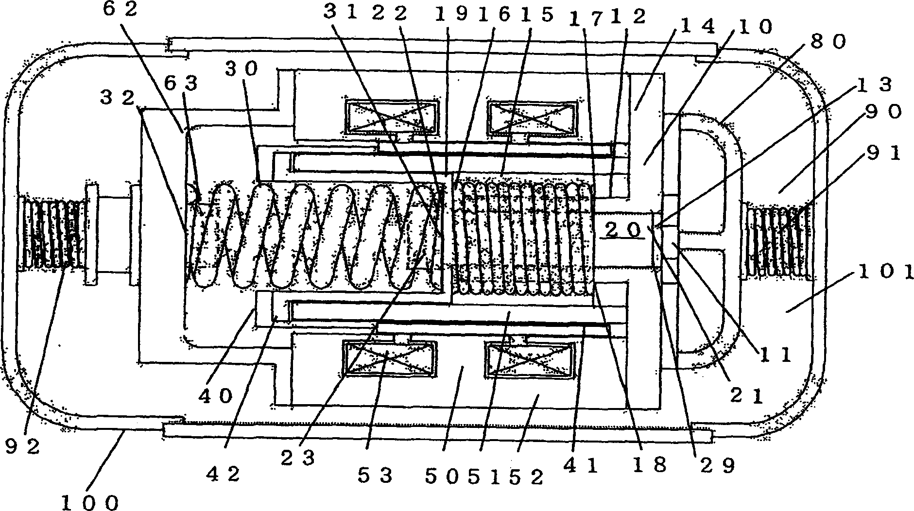
[0021] Next, an embodiment of the linear compressor of the present invention will be described with reference to the drawings. first according to figure 1 The overall structure of the linear compressor of the present invention will be described.

[0022] Generally, the linear compressor consists of a cylinder body 10, a piston 20, a movable part 40 and a fixed part 50 constituting a linear motor part, a spring mechanism part formed by a coil spring, an end cover part 80, a support mechanism part 90, an airtight container 100 poses.

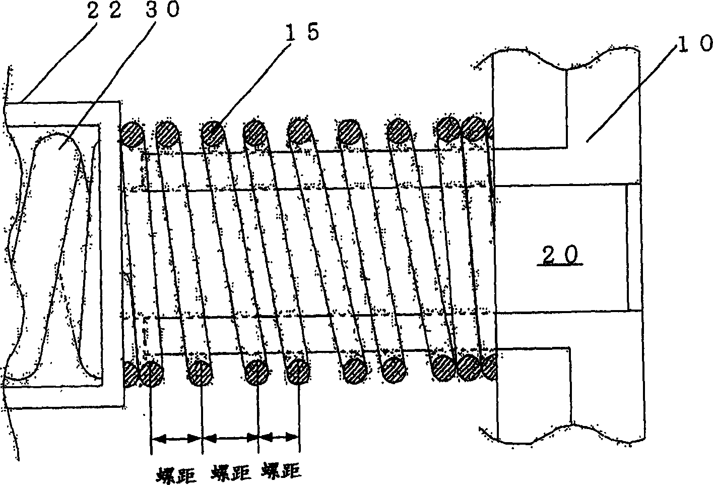
[0023] The cylinder 10 is composed of a cylinder end surface 11 on which a valve body (not shown) is attached, a flange portion 14, and a protrusion 12 protruding from the flange portion 14 in one direction (left direction in the figure). The piston 20 has a frame body 22 processed with recesses for accommodating the post portion 21 and the coil spring 30 . A protrusion 23 is provided on the inner bottom surface of the concave portion of the fr...


PUM


Abstract

A linear compressor comprises a cylinder 10, a piston 20, a cylinder end surface 11, a movable section 40 and a stationary section 50 that constitute a linear motor, coil springs 15, 30, a head cover 80, a support mechanism 90, a sealed container 100, etc. Defined in the cylinder 10 is a compression chamber 13 for gas compression. The spring member 61 of a spring mechanism member 60 is composed of coil springs 15, 30 having predetermined spring rigidity. When the coil spring 15 is compressed to the fullest extent, a clearance is secured between the end surface of the piston 20 and the cylinder end surface 11, whereby the amplitude of the piston 20 of the linear compressor can be controlled.

Description

technical field [0001] The invention relates to a linear compressor which uses a linear motor to drive a piston fitted inside a cylinder to reciprocate to compress gas. Background technique [0002] For the refrigeration cycle, HCFC-based refrigerants represented by R22 are considered to destroy the ozone layer due to the stability of their physical properties. In recent years, although HRC-based refrigerants have been adopted as a substitute for HCFC-based refrigerants, these refrigerants have a property of increasing global warming. Therefore, recently, HC-based refrigerants that do not have a large impact on the ozone layer and global warming have begun to be used. However, since the HC-based refrigerant is flammable, it is necessary to prevent explosion and fire in order to ensure safety, and therefore the usage of the refrigerant is required to be as small as possible. In addition, HC-based refrigerants themselves have no lubricity and have the property of being easil...

Claims


Application Information

Patent Timeline
IPC IPC(8): F04B35/04
CPCF04B35/045F04B17/04
Inventor 赤泽辉行河原定夫小川信明长谷川宽
Owner PANASONIC CORP
Why Eureka
Try Eureka