Bar code scanner and its bar cod scanning method

A barcode scanner and barcode technology, applied in the field of barcode scanners and barcode scanning, can solve the problems of inability to achieve high recognition ability, high price, complex assembly process, etc., and achieve long-distance code reading and simple structure , the effect of strong resolution

Active Publication Date: 2005-03-02
杜瑞
View PDF1 Cites 16 Cited by
  • Summary
  • Abstract
  • Description
  • Claims
  • Application Information

AI Technical Summary

Problems solved by technology

[0005] Although the design of the barcode scanning device 10 seems very straightforward, the process of its output is very complicated when actually manufacturing these devices, thus making its price high, especially because the four LED light sources 22 must be installed near the scanning The volume of the reading head 24 and the reading lens 26 must be very small, so its specifications are special and the price is also high. At the same time, since the four LED light sources 22 are close to the front end to scan the reading head 24, its power supply must be provided by the rear end. The circuit board 14 is additionally connected to the power cord 21 for supply, and the power cord 21 must also be welded during assembly.
Lenses 18 and 26 must be manually assembled due to their small size, which further complicates the assembly process.
In addition, the barcode scanning device is still unable to achieve fast, long-distance code reading and decoding with high recognition capability.

Method used


Image

  • Bar code scanner and its bar cod scanning method
  • Bar code scanner and its bar cod scanning method
  • Bar code scanner and its bar cod scanning method

Examples


Embodiment Construction

[0055] The present invention will be described in further detail below in conjunction with accompanying drawing:

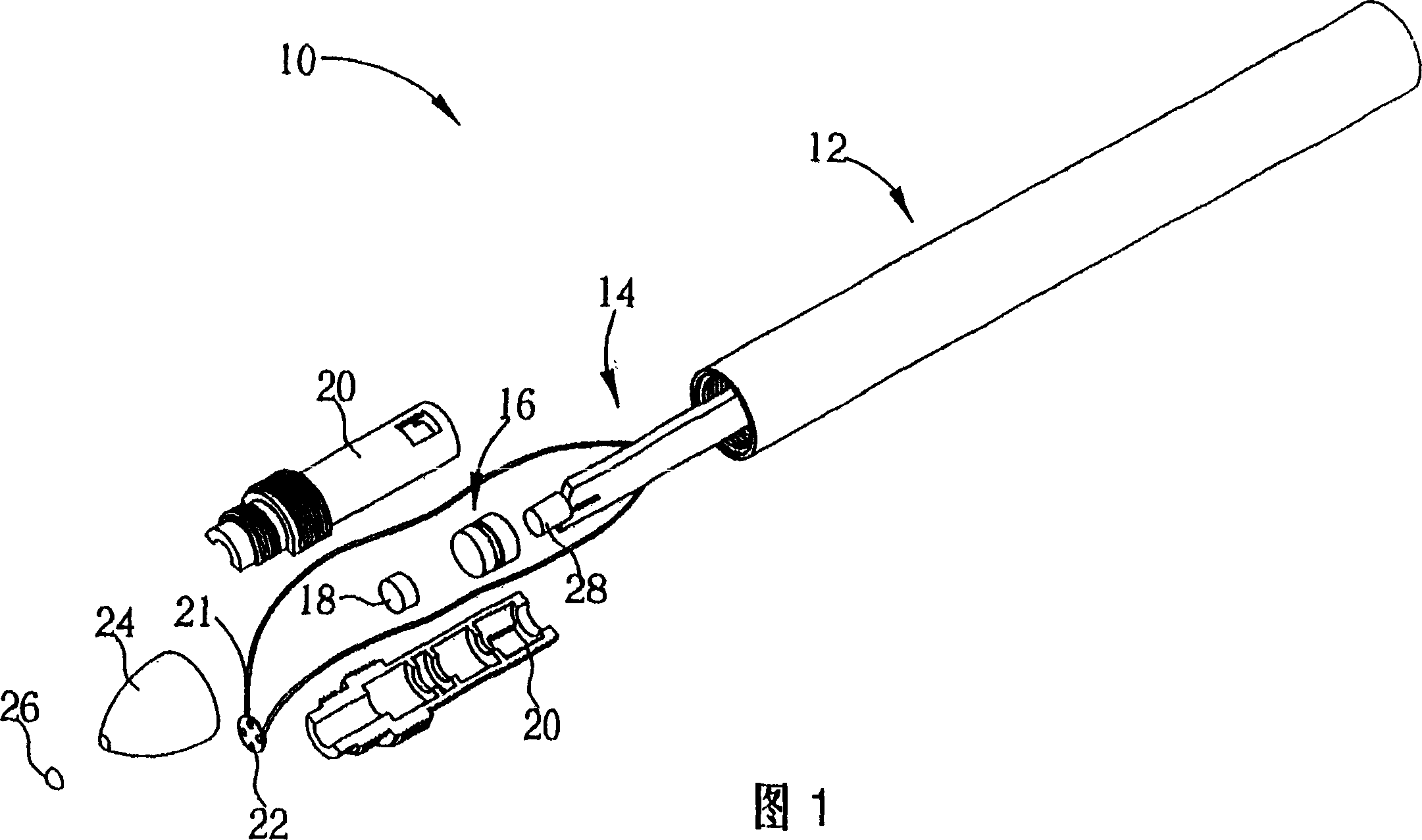
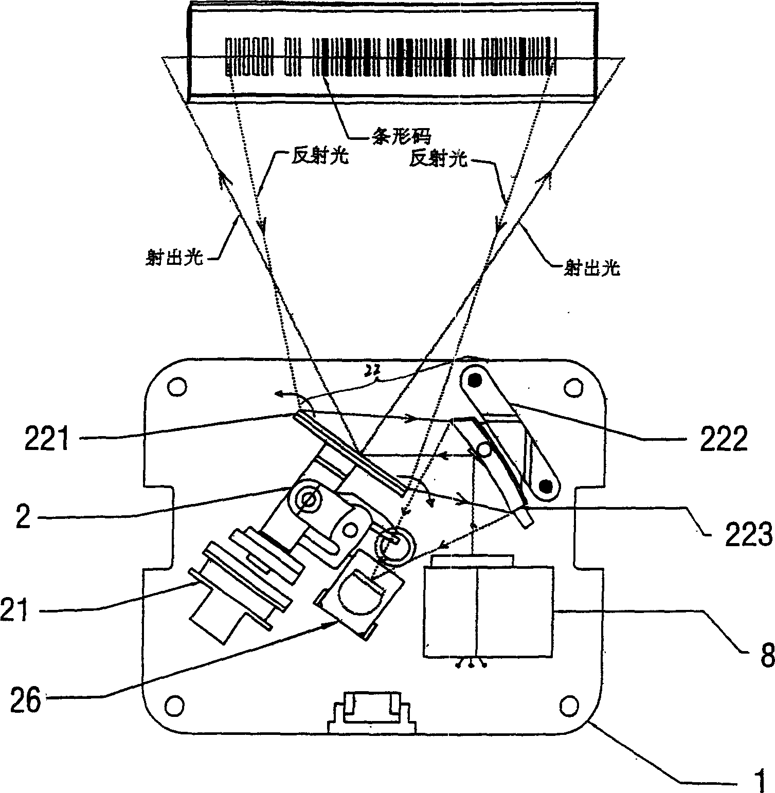
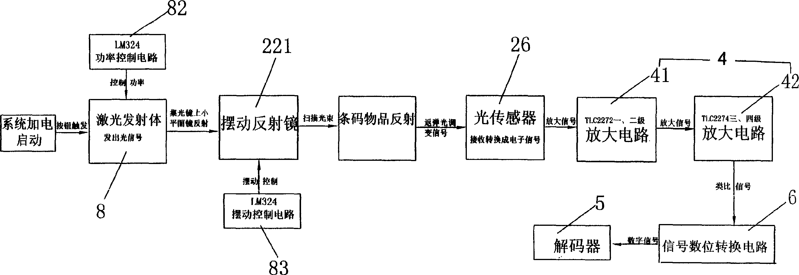
[0056] Please refer to the attached picture, the barcode scanner contains:

[0057] The printed circuit board 1 arranged in the casing includes:

[0058] The optical sensor 26 at the middle end of the front of the printed circuit board 1 is used to receive a modulated rebound light signal and convert it into a corresponding electronic signal; There is a swing coil 21, the swing reflector 221 in front of the swing device 2 and the spherical light-collecting reflector 223 positioned on the side by a fixed clip 222 constitute a light-collecting reflector 22. The hole 2222 is composed. The oscillating reflector 221 guides the light spot emitted by the laser emitter 8 to the oscillating reflector 221 to form a scanning beam, and the spherical light-collecting reflector 223 guides the reflected light on the barcode back to the light sensor 26; The oscillating mirror ...


PUM


Abstract

The invention relates to a lamp house and light sensor which are arranged with a single circuit board, and the code reading speed is quick, the identification performance is high, strong resolution and high precision, it has a bar code scanner capable of quickly long distance reading code. The bar code scanner includes a printed circuit board, there is a semiconductor laser diode power source on the circuit board, a scanning light reflection guide device, a light swing reflector and a light sensor, pendulum driving coil and a set of signal control and process circuit, the light from the laser diode is guided to the pendulum reflecting mirror through the small mirror on the light collector and forms parallel scanning beam with time difference, and it scans the object bar code on the front end of the circuit board and forms light rebounding signal, and the signal is concentrated onto the light sensor through the collector in order to be checked, then a demodulating amplification filter circuit processes the signal acquired by the light sensor into correspondent bar code signal.

Description

technical field [0001] The invention relates to a barcode scanner and a barcode scanning method thereof. Background technique [0002] Barcode scanning devices are now commonly used in supermarkets or stores to efficiently process goods whose item numbers or prices are coded with barcodes. The operating principles of barcode scanning devices can be seen in many previous technologies, such as: Publication No. 179959 Taiwan Patent, or US Patent No. 5,932,860, however, the internal design of these prior art barcode scanning devices is relatively very complicated. [0003] Please refer to FIG. 1 , which is an exploded view of a conventional pen-shaped barcode scanning device 10 . The conventional barcode scanning device 10 includes a housing 12 and a circuit board 14 disposed in the housing 12 , the circuit board includes a light sensor 28 and a control circuit (not shown). The casing 12 further includes a pupil 16 , a lens 18 , a light source 22 , and a positioning component ...

Claims


Application Information

Patent Timeline
Patent Type & Authority Applications(China)
IPC IPC(8): G06K7/00G06K7/10
Inventor 杜瑞
Owner 杜瑞
Why Eureka
Try Eureka