Multi-path connecting terminal for communication cable and its producing method and connecting method
A technology for communication cables and connectors, applied in the field of four-wire connectors for communication cables, can solve the problems of loose cable cores, inconvenient observation of the connection quality of the cable cores, damage to the cable cores, etc., and achieves low comprehensive cost. , The operation process is clearly visible, and the effect of construction quality assurance
- Summary
- Abstract
- Description
- Claims
- Application Information
AI Technical Summary
Problems solved by technology
Method used
Image
Examples
Embodiment 1
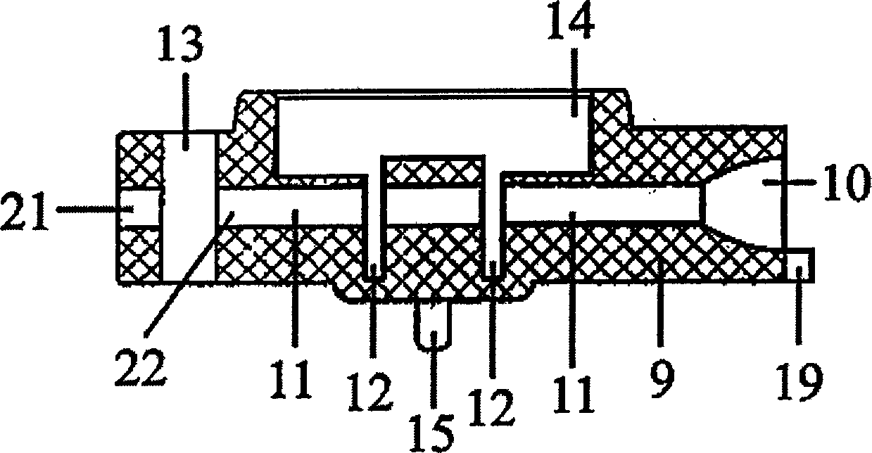
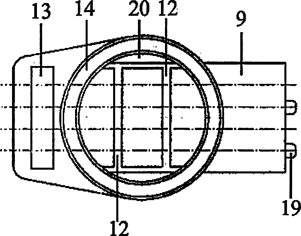
[0053] In the base (9), four wiring channels (11) are arranged relatively parallel to the base (9), and the wiring channels (11) penetrate from the front end of the base (9) to the rear end of the base (9), The port of the wiring channel (11) at the front end of the base (9) is provided with an extended mouth-shaped inlet guide (10), and the port of the wiring channel (11) at the rear end of the base (9) is provided with a test hole (21). The rear end of the base (9) is provided with a disconnection hole (13), and the disconnection hole (13) runs through the rear end of the base (9) relatively vertically with the wiring channel (11), and the wiring channel (11) and the disconnection hole ( 13) An outlet port (22) is provided at the intersection, and the wire inlet guide port (10), the wiring tunnel (11), the outlet port (22) and the test hole (21) are on the same axis. The front end of the base (9) is relatively parallel with several wire inlet marks (19), and the wire inlet m...
Embodiment 2
[0056] 6 wiring channels (11) are arranged relatively parallel to the base (9) in the base (9), and the wiring channels (11) penetrate from the front end of the base (9) to the rear end of the base (9), The port of the wiring channel (11) at the front end of the base (9) is provided with an extended mouth-shaped inlet guide (10), and the port of the wiring channel (11) at the rear end of the base (9) is provided with a test hole (21). The rear end of the base (9) is provided with a disconnection hole (13), and the disconnection hole (13) runs through the rear end of the base (9) relatively vertically with the wiring channel (11), and the wiring channel (11) and the disconnection hole ( 13) An outlet port (22) is provided at the intersection, and the wire inlet guide port (10), the wiring tunnel (11), the outlet port (22) and the test hole (21) are on the same axis. The front end of the base (9) is provided with a plurality of wire inlet marks (19) relatively parallel to each o...
Embodiment 3
[0059] In the base (9), four wiring channels (11) are arranged relatively parallel to the base (9), and the wiring channels (11) penetrate from the front end of the base (9) to the rear end of the base (9), The port of the wiring channel (11) at the front end of the base (9) is provided with an extended mouth-shaped inlet guide (10), and the port of the wiring channel (11) at the rear end of the base (9) is provided with a test hole (21). The rear end of the base (9) is provided with a disconnection hole (13), and the disconnection hole (13) runs through the rear end of the base (9) relatively vertically with the wiring channel (11), and the wiring channel (11) and the disconnection hole ( 13) An outlet port (22) is provided at the intersection, and the wire inlet guide port (10), the wiring tunnel (11), the outlet port (22) and the test hole (21) are on the same axis. The front end of the base (9) is relatively parallel with several wire inlet marks (19), and the wire inlet m...
PUM
 Abstract
Description
Claims
Application Information
 - R&D
- Intellectual Property
- Life Sciences
- Materials
- Tech Scout
- Unparalleled Data Quality
- Higher Quality Content
- 60% Fewer Hallucinations
Browse by: Latest US Patents, China's latest patents, Technical Efficacy Thesaurus, Application Domain, Technology Topic, Popular Technical Reports.
© 2025 PatSnap. All rights reserved.Legal|Privacy policy|Modern Slavery Act Transparency Statement|Sitemap|About US| Contact US: help@patsnap.com


