
Acceleration sensor

An acceleration sensor, acceleration sensing technology, applied in the direction of measuring acceleration, speed/acceleration/impact measurement, acceleration measurement using inertial force, etc., can solve problems such as the change of acceleration sensor characteristics, and achieve the effect of preventing characteristic changes

Inactive Publication Date: 2005-03-09
MITSUBISHI ELECTRIC CORP
View PDF1 Cites 0 Cited by
  • Summary
  • Abstract
  • Description
  • Claims
  • Application Information

AI Technical Summary

Problems solved by technology

[0004] However, according to the above-mentioned structure, since the acceleration sensing element and the frame are formed together on the semiconductor substrate, cracks may be caused in the joint region between the cover part and the frame due to external force, or the material of the cover part and the frame is different in the joint area. The residual stress that exists due to the difference in thermal expansion coefficient between the two is easy to propagate to the acceleration sensor element, and as a result, the characteristics of the acceleration sensor may change

Method used


Image

  • Acceleration sensor
  • Acceleration sensor
  • Acceleration sensor

Examples


Embodiment Construction

[0033] Embodiments according to the present invention will be described below with reference to the drawings.

[0034] Implementation form 1:

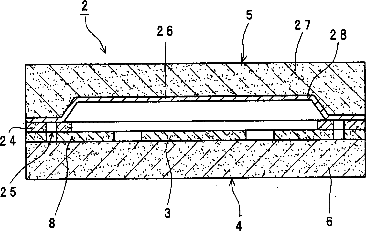
[0035] figure 1 It is a cross-sectional view of Embodiment 1 according to the present invention. The acceleration sensor 2 includes a base portion 4 for carrying the acceleration sensor element 3 , and a cover portion 5 joined to the base portion 4 for sealing the acceleration sensor element 3 .

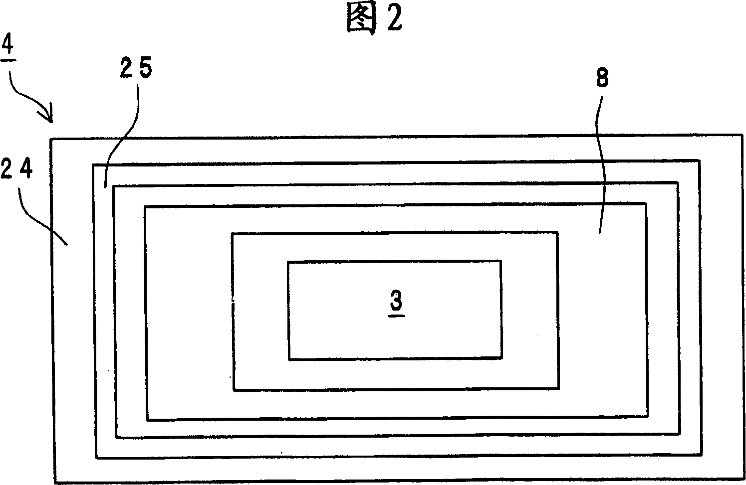
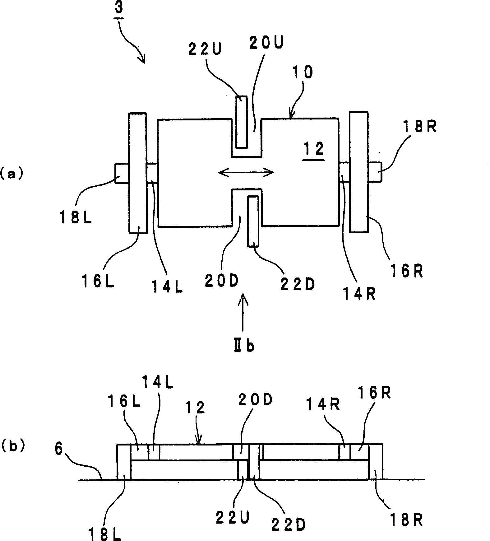
[0036] FIG. 2 is a plan view of the base portion 4 . The base portion 4 is provided with a rectangular semiconductor silicon substrate 6 (a substrate in a broad sense), on the principal surface of which, a sensor element 3 for detecting acceleration and a frame 8 surrounding the sensor element 3 are provided. The frame 8 is generally rectangular, and the invention is not limited by its shape. The acceleration sensing element 3 and the frame 8 are formed, for example, by depositing a polysilicon layer doped with phosphorus as an impurity o...


PUM


Abstract

An acceleration sensor includes an acceleration sensor element and a frame portion surrounding the element. The sensor element and the frame portion are located on a major surface of a substrate. An intermediate layer is formed on the frame portion. A cap portion is bonded to the intermediate layer, thereby sealing-off the acceleration sensor element. Grooves in the form of a frame are provided in the frame portion and the intermediate layer, respectively, and located at positions generally identical to each other with regard to the major surface direction of the substrate.

Description

technical field [0001] The invention relates to an acceleration sensor. technical background [0002] At present, the known acceleration sensor is that the acceleration sensing element and the frame surrounding the sensing element are arranged on the semiconductor substrate, and the encapsulation part is bonded on the frame, thereby the acceleration sensing element is sealed (for example, refer to the patent document 1). [0003] Patent Document 1: JP-A-2002-134759 [0004] However, according to the above-mentioned structure, since the acceleration sensing element and the frame are formed together on the semiconductor substrate, cracks may be caused in the joint area between the cover part and the frame due to external force, or the material of the cover part and the frame is different in the joint area. The residual stress present due to the difference in thermal expansion coefficient between the two tends to propagate to the acceleration sensor element, and as a result, ...

Claims


Application Information

Patent Timeline
Patent Type & Authority Applications(China)
IPC IPC(8): B81B7/00G01P1/02G01P15/08G01P15/125H01L29/84
CPCB81B7/0051G01P2015/0814B81B2201/0235G01P15/125G01P15/0802B81C2203/0109G01P1/026
Inventor 山口靖雄中村邦宏
Owner MITSUBISHI ELECTRIC CORP
Learn More