Illumination apparatus employing auxiliary light source and projection system including illumination apparatus

A technology for lighting devices and auxiliary light sources, which is applied to components of lighting devices, lighting devices, optical elements for changing the spectral characteristics of emitted light, etc., and can solve problems such as difficulties in color filters and insufficient compensation

Inactive Publication Date: 2005-03-09
SAMSUNG ELECTRONICS CO LTD
View PDF1 Cites 15 Cited by
  • Summary
  • Abstract
  • Description
  • Claims
  • Application Information

AI Technical Summary

Problems solved by technology

However, it is difficult to manufacture such a color filter 17
In addition, the display 1 with the color filter 17 compensates for the deficiency in the spatial distribution, but cannot compensate for the deficiency in the light intensity distribution of the light emitted from the UHP lamp 5

Method used


Image

  • Illumination apparatus employing auxiliary light source and projection system including illumination apparatus
  • Illumination apparatus employing auxiliary light source and projection system including illumination apparatus
  • Illumination apparatus employing auxiliary light source and projection system including illumination apparatus

Examples


Embodiment Construction

[0035] The present invention will be described more fully with reference to the accompanying drawings, in which exemplary embodiments of the invention are shown. The described exemplary embodiments are intended to aid the understanding of the present invention and are not intended to limit the scope of the present invention in any way. The same reference numerals denote the same elements throughout the drawings.

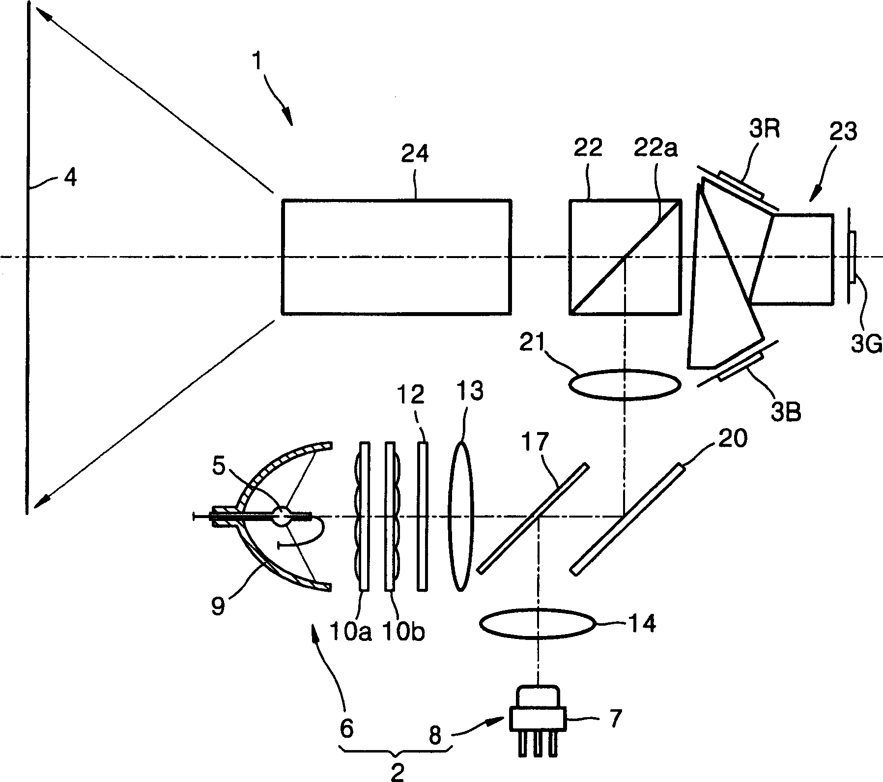
[0036] see Figure 5 , The lighting device 48 according to the first exemplary embodiment of the present invention includes: a light source part 211; an integrating part 44, which includes first and second light beams for integrating the light beam emitted by the light source 211 so as to obtain a uniform light intensity distribution. Integrators 44a and 44b; an ultraviolet filter 49 disposed on a path between the light source portion 211 and the integrating portion 44 for filtering ultraviolet light; and disposed on a central portion of the ultraviolet filter 49 fo...


PUM


Abstract

Provided are an illumination apparatus employing an auxiliary light source and a projection system therewith. The illumination apparatus includes a main light source unit for emitting white light, and an auxiliary light source unit for introducing auxiliary light of a predetermined wavelength band to a space in which the light intensity of the main light source unit is low to increase the intensity of the white light. The illumination apparatus can uniformly control a spatial light intensity distribution and a band light intensity distribution, and enlarge a color reproduction area and provide a high quality image with high luminous efficiency.

Description

technical field [0001] The present invention relates to an illuminating device and a projection system, more particularly, the present invention relates to an illuminating device using an auxiliary light source and a projection system comprising the illuminating device. Background technique [0002] figure 1 is a schematic diagram showing the structure of a light source used in a projection system of the related art. see figure 1 , the light source 2 includes a lamp 5 and a parabolic reflector 9 . Lamp 5 is a mercury, xenon or metal halide lamp. The light beam emanating from the lamp 5 diverges in the space between the lamp 5 and the parabolic reflector 9 of the light source 2 . [0003] figure 2 yes figure 1 The light intensity distribution diagram and distribution table of the light source 2 shown. see figure 2 , since the light is not emitted from the point where the central electrode provided on the lamp 5 is located, the brightness of the central position is d...

Claims


Application Information

Patent Timeline
Patent Type & Authority Applications(China)
IPC IPC(8): G02B27/28F21V9/00G02B5/00G02B6/00G03B21/00G03B21/14G03B21/20H04N9/31
CPCH04N9/3197H04N9/3117H04N9/315G02B27/28
Inventor 金大式赵虔皓金成河
Owner SAMSUNG ELECTRONICS CO LTD
Why Eureka
Try Eureka