Digitalized design method of rubber product extrusion die
A rubber product and design method technology, applied in the direction of electrical digital data processing, calculation, special data processing applications, etc., can solve problems such as extrusion molding process analysis, improve product performance and quality, reduce production costs, and shorten development cycle effect
- Summary
- Abstract
- Description
- Claims
- Application Information
AI Technical Summary
Problems solved by technology
Method used
Image
Examples
Embodiment 1
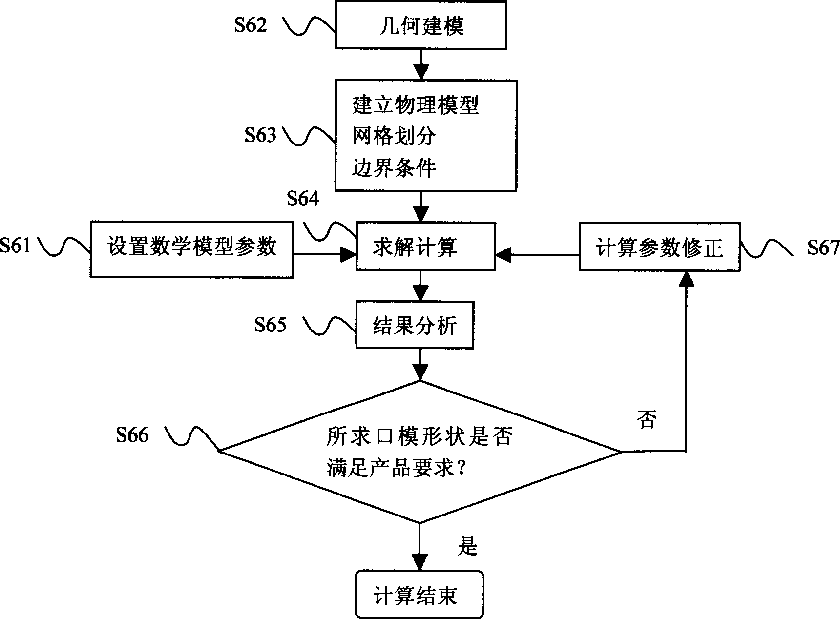
[0020] refer to image 3 Explain that the present invention calculates the shape of the extruded product according to the geometric shape of the mold, and determines the deformation law of the extruded product.
[0021] 1 Establishing a mathematical model (S61)
[0022] Usually rubber melt can be simplified as a viscoelastic incompressible fluid, and its flow governing equation can be expressed as
[0023] Mass Conservation Equation:
[0024] ·v=0
[0025] Momentum Conservation Equation:
[0026] Re dv dt = - ▿ · p + ▿ · τ + f
[0027] Where v is the velocity, Re is the Reynolds quasi-number, p is the pressure, f is the body force, and τ is the deviatoric stress when the viscoelastic fluid flows.
[0028] fluid constitutive equation
[0029] The rubber melt can be represented by the Phan-Thien-Tanner (PTT)...
Embodiment 2
[0052] refer to image 3 Description The present invention calculates the geometry of the die based on the desired shape of the extrudate (ie, the shape of the article).
[0053] The geometry of the mold is calculated according to the shape of the extrudate, and the calculation process is basically the same as that of Example 1. The calculation steps of Example 1 are S61-S65, and the calculation steps of Example 2 are increased by S66 and S67. Calculation step S66 is to judge whether the required die shape satisfies the design requirements according to the calculation results. If the requirements are met, the calculation ends; if not, the calculation parameters are corrected (S67), and S65 is repeated until the design requirements are met. Figure 7 is the die shape calculated from the shape of the extrudate.
[0054] Since the calculation purposes of Embodiment 2 and Embodiment 1 are different, their grid reset areas are different. For the area settings, see Figure 5 .
...
Embodiment 3
[0058] image 3 The setting mathematical model parameters (S61) in the description of the determination method of the constitutive model parameters of different rubber materials.
[0059] In order to determine the constitutive model parameters, the following rheological experiments are required:
[0060] (1) Capillary rheometer experiment: used to determine the relationship between shear rate and viscosity in the high shear rate range;
[0061] (2) Rotational rheometer experiment: used to determine the relationship between shear rate and viscosity in the low shear rate range;
[0062] The parameters in the constitutive model can be obtained by fitting the rheological experimental data of the rubber material. Table 1 shows the material parameters of the PTT model of EPDM and SBR, which can be used to simulate the rubber extrusion process. Figure 6 and Figure 7 is the calculation result obtained from the material parameters of EPDM in Table 1 using the PTT model.
[0063]...
PUM
 Abstract
Description
Claims
Application Information
 - R&D
- Intellectual Property
- Life Sciences
- Materials
- Tech Scout
- Unparalleled Data Quality
- Higher Quality Content
- 60% Fewer Hallucinations
Browse by: Latest US Patents, China's latest patents, Technical Efficacy Thesaurus, Application Domain, Technology Topic, Popular Technical Reports.
© 2025 PatSnap. All rights reserved.Legal|Privacy policy|Modern Slavery Act Transparency Statement|Sitemap|About US| Contact US: help@patsnap.com


