

Cyclic superimposed chopper energy-saving pulse power source for spark machining
A pulse power supply and electric spark technology, applied in electric processing equipment, metal processing equipment, circuits, etc., can solve the problems of energy-saving pulse power supply pulse electric parameter adjustment range limitation and other issues
- Summary
- Abstract
- Description
- Claims
- Application Information
AI Technical Summary
Problems solved by technology
Method used
Image

Examples
specific Embodiment approach 1
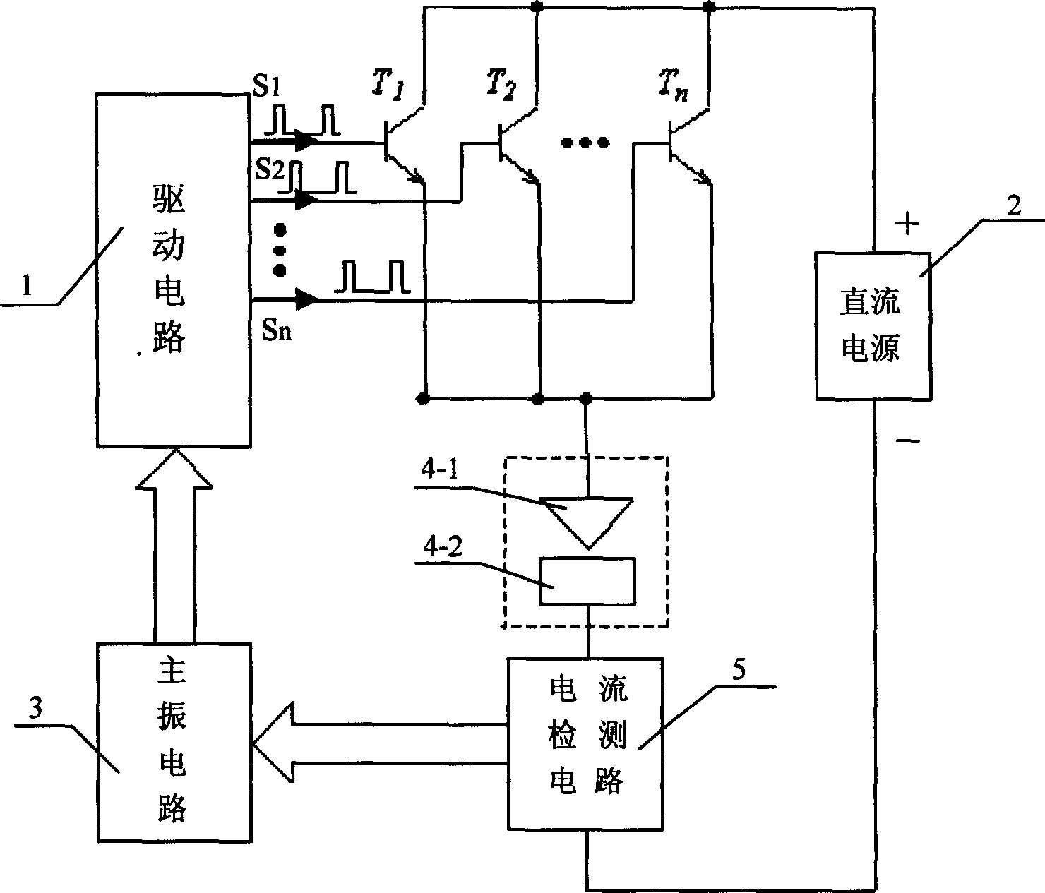
[0005] Specific implementation mode one: the following combination Figure 1 to Figure 3 This embodiment will be specifically described. It consists of a DC power supply 2, a main vibration circuit 3, a drive circuit 1, and several power switch tubes (T 1 ~T n ) and the processing electrode 4-1 of electric discharge machining and the workpiece 4-2 are composed, and the positive output terminal of the DC power supply 2 is connected to the power switch tube (T 1 ~T n ) on the collector, the power switch tube (T 1 ~T n ) is connected to the processing electrode 4-1, the workpiece 4-2 is connected to the negative output terminal of the DC power supply 2, the output terminal of the main vibration circuit 3 that generates the pulse signal is connected to the input terminal of the drive circuit 1, and some of the drive circuit 1 The output ports respectively output the pulse signal S 1 , S 2 …S n , pulse signal S 1 , S 2 …S n respectively applied to the power switch tube T...
specific Embodiment approach 2
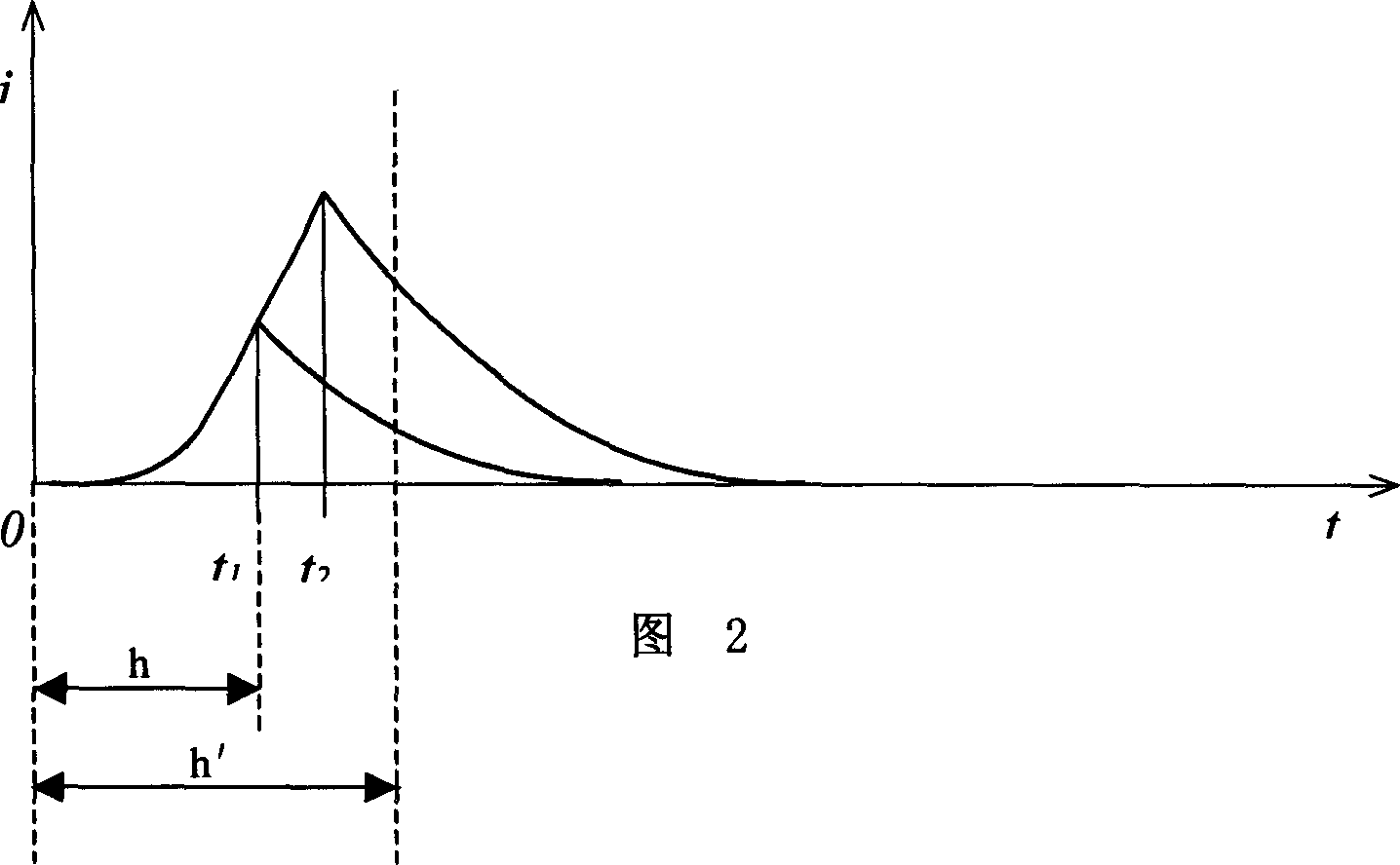
[0006] Specific embodiment two: below in conjunction with Fig. 2 to Figure 7 This embodiment will be specifically described. This embodiment also includes a current detection circuit 5, the current detection circuit 5 is connected in series between the workpiece 4-2 and the DC power supply 2 to extract the current signal, the main vibration circuit 3 is composed of a single-chip microcomputer 3-1 and a programmable logic device 3-2, The output end of the current detection circuit 5 is connected to the input end of the single-chip microcomputer 3-1 of the main vibration circuit 3, the output end of the single-chip microcomputer 3-1 is connected to the input end of the programmable logic device 3-2, and the output end of the programmable logic device 3-2 Connect to the input terminal of drive circuit 1. The single-chip microcomputer 3-1 is used to analyze the preset parameters in the single-chip microcomputer 3-1 and the current signal detected by the current detection circuit...
specific Embodiment approach 3
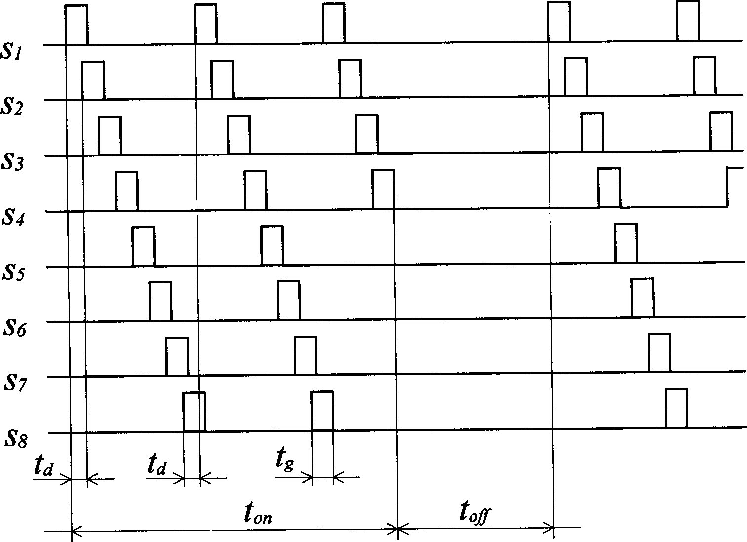
[0007] Specific implementation mode three: the following combination image 3 This embodiment will be described concretely through FIG. 6 . The difference between this embodiment and Embodiment 1 is that for the power switch tube (T 1 ~T n) when performing drive chopping, the last power switch tube T in one drive cycle n The set delay time t after the drive signal arrives d After that, the power switch tube T 1 The drive signal arrives to start the next drive cycle. Other components and connections are the same as those in Embodiment 1. Such arrangement saves the number of power switch tubes.
PUM
 Abstract
Description
Claims
Application Information