Method of sealing in small spatial obstructs at entrance end of tin pot in product line float glass, and seal structure

A float glass and production line technology, applied in the field of float glass production, can solve the problems of lower production stability, lower glass quality, attenuation of pure nitrogen flow stiffness, etc. material reduction effect

Inactive Publication Date: 2005-03-30
LUOYANG GLASS
View PDF0 Cites 17 Cited by
  • Summary
  • Abstract
  • Description
  • Claims
  • Application Information

AI Technical Summary

Problems solved by technology

[0006] 4. The sealing effect of the inlet end is poor, so that the pressure control in the tin bath is severely restricted
However, since the span here is generally about 2-3 meters, there is no isolation between the launder and the tin tank on the structure, and the space between the nitrogen and the tin tank is also in an unobstructed communication state. The tanks are connected to each other. After the pure nitrogen gas is blown in from both sides, it quickly mixes with the gas in the tank, and cannot form a gas wall that prevents the gas from escaping. In addition, the stiffness of the pure nitrogen flow from the nitrogen bag increases with the injection pressure. The output distance increases and attenuates quickly, so the pure nitrogen flow in the middle is easily broken by the gas in the tank, and it is difficult to form a pure nitrogen wall
Since the gas in the tank itself has a certain pressure, by calculation, 200Bm on each side 3 The pure nitrogen flow rate per hour cannot guarantee the requirement of full partition, and the passage of a large amount of gas at too low temperature will have a serious impact on the temperature uniformity of the molten glass, which will reduce the quality of the glass and reduce the stability of production.
Therefore, the method of increasing the nitrogen flow rate in large quantities cannot be adopted
Therefore, this form of structure cannot meet the purpose of separating the inlet end and the atmosphere of the tin bath in the production line from the actual application situation.

Method used


Image

  • Method of sealing in small spatial obstructs at entrance end of tin pot in product line float glass, and seal structure
  • Method of sealing in small spatial obstructs at entrance end of tin pot in product line float glass, and seal structure
  • Method of sealing in small spatial obstructs at entrance end of tin pot in product line float glass, and seal structure

Examples


Embodiment Construction

[0023] In conjunction with accompanying drawing, embodiment of the present invention is described as follows:

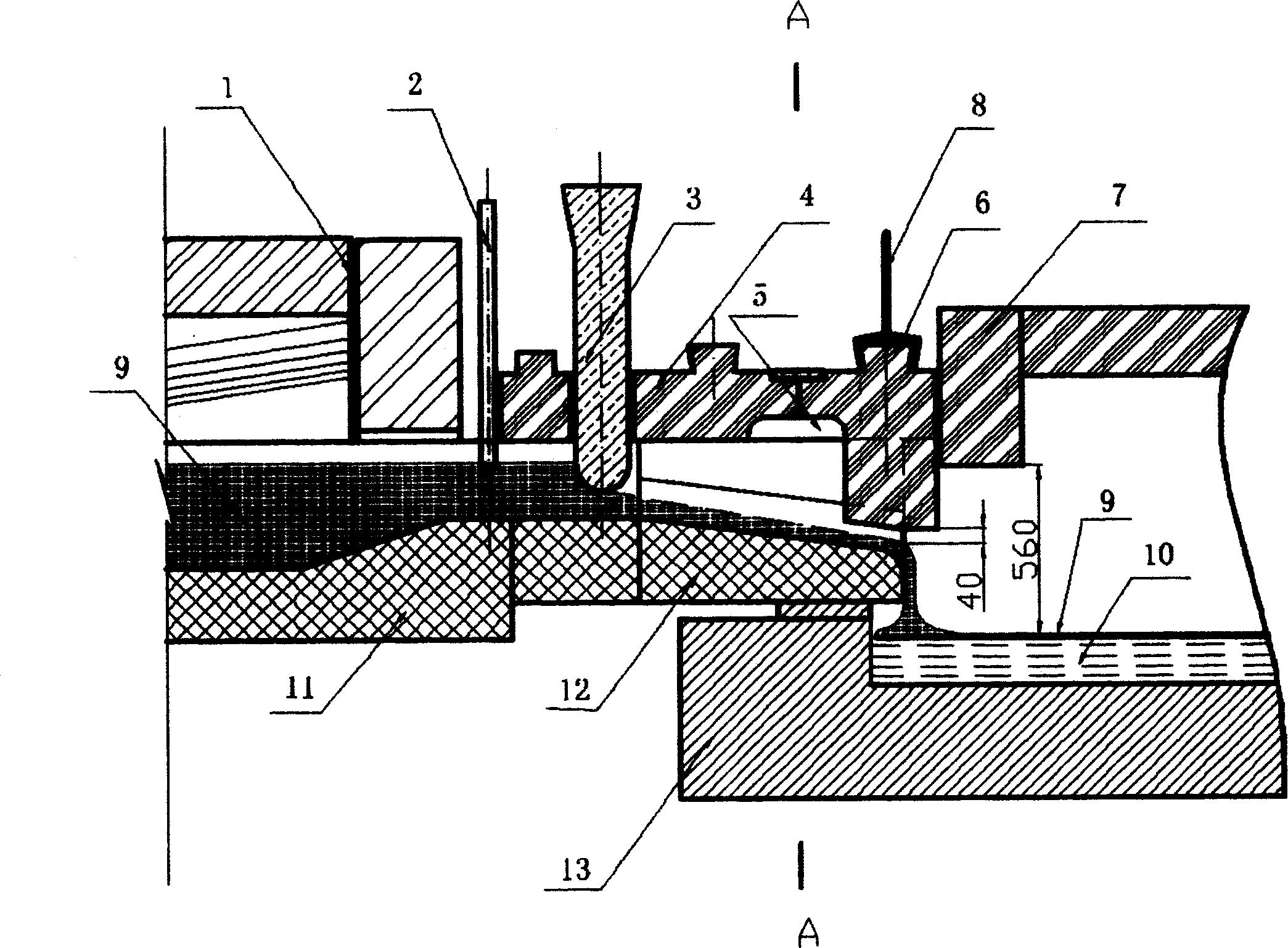
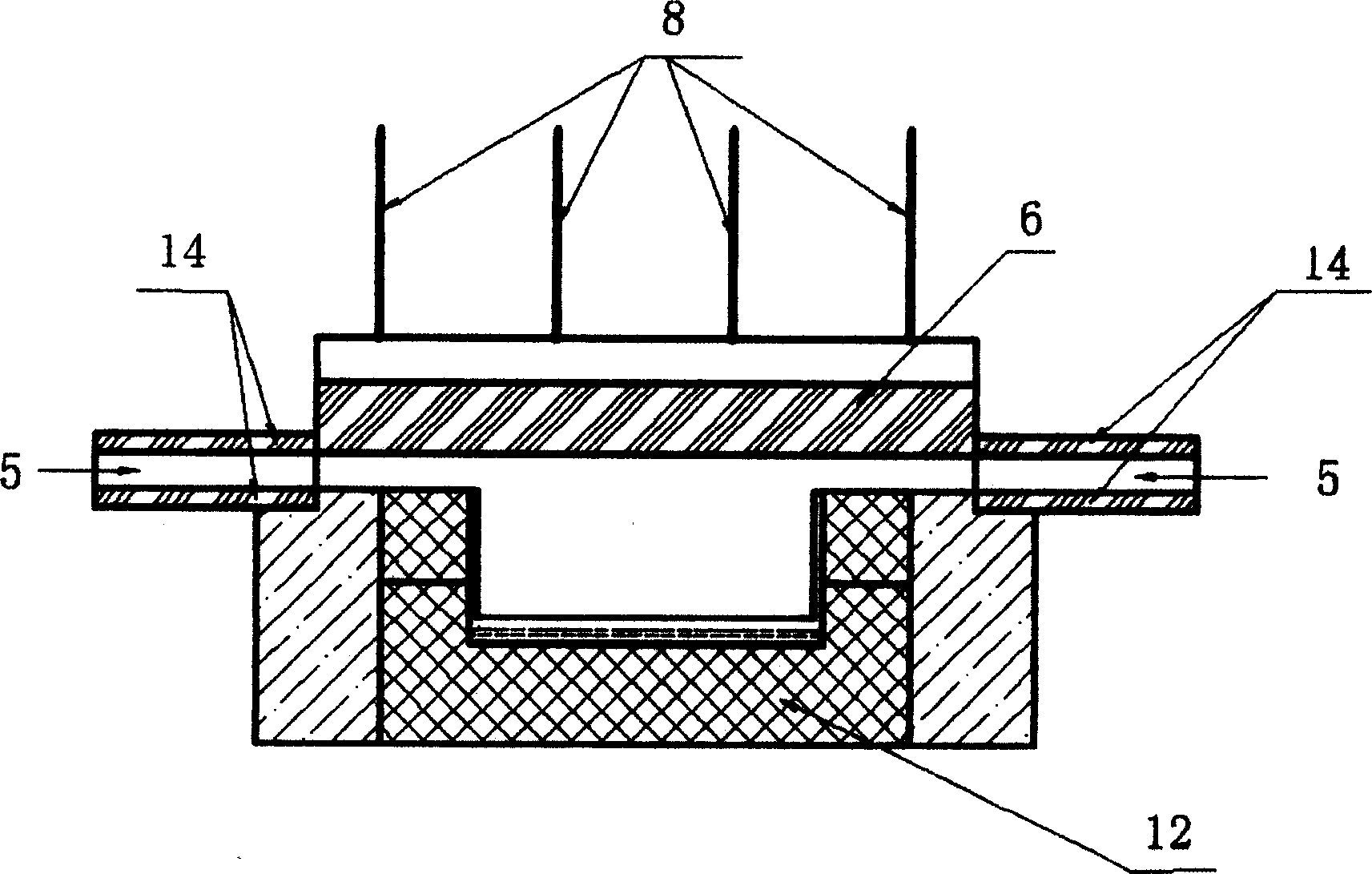
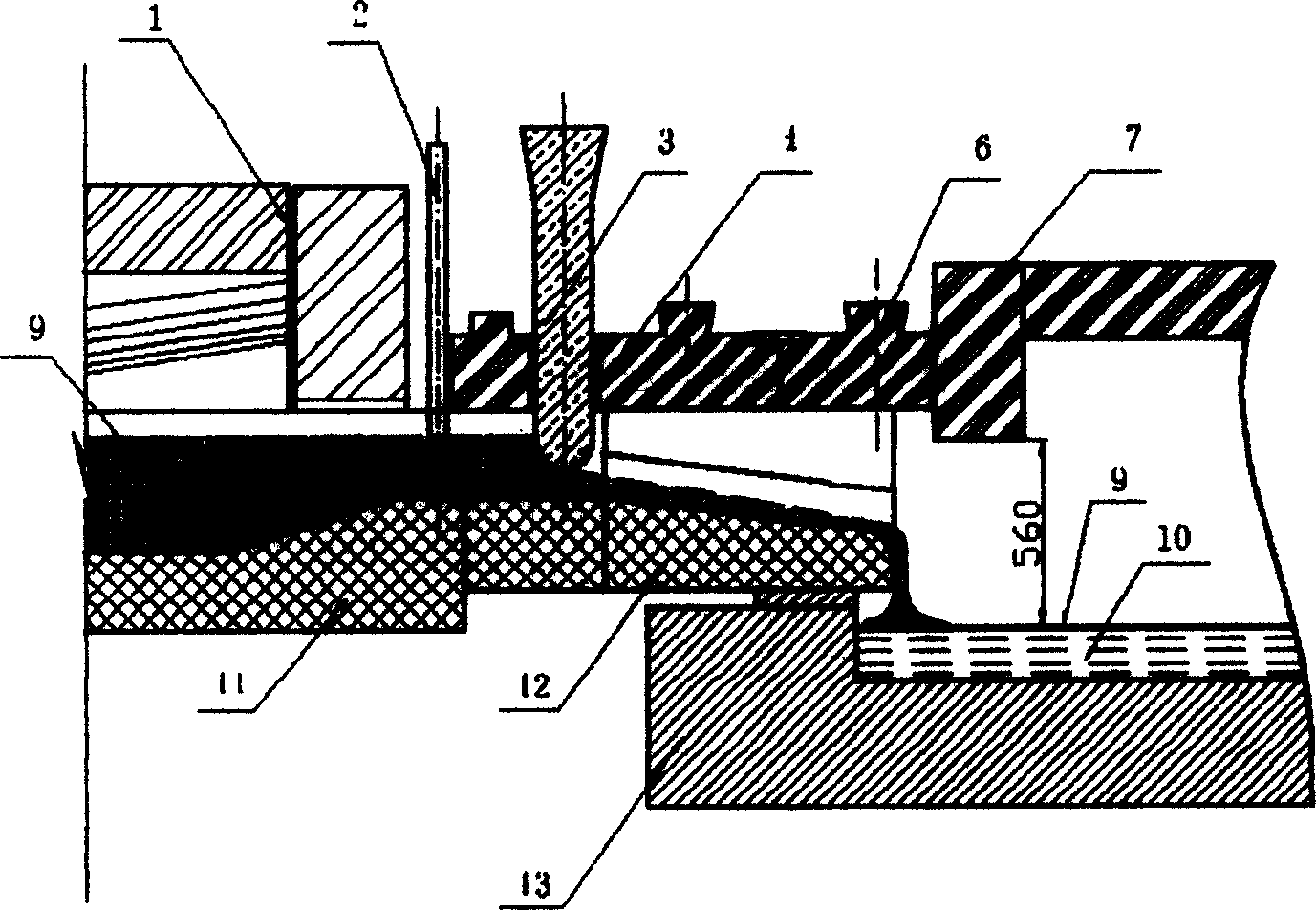
[0024] Such as figure 1 , 2 As shown, by setting a separation wall between the launder and the tin launder, a small air-permeable gap is formed between the tin ladle and the launder, and the upper part of the launder between the flow gate 3 and the separation wall 6 The space constitutes a closed space with only a small air gap. Nitrogen gas is introduced from both sides to the upper space between the flow gate and the separation wall. In this space, that is, the space above the launder, a pure nitrogen sealing area is formed. Taking a float glass production line with a melting capacity of 300 tons as an example, the amount of nitrogen introduced on each side is 15Bm 3 / h, the gas pressure of 50Pa can be formed in the upper space of the launder, which is greater than the pressure of the tin bath and the cooling part of the melting furnace, which can effectively pr...


PUM


Abstract

In the invention, the way of setting separating wall is used to block flowing tank and molten tin bath effectively to form a closed spce with small air gap above the flowing tank between flow flashboard and separating wall, purity nitrogen closed are in the space and make the space pressure being more than pressure in molten tin bath and cooling part of melting furnace, principle of pressure balance is utilized to prevent that gas in molten tin bath is escaped and condensed surrounding the flow flashboard and gas in melting furnace gets into the molten tin bath,

Description

Technical field [0001] The invention belongs to the float glass production technology, and mainly relates to a small space partition sealing method and a sealing structure at the inlet end of a tin tank of a float glass production line. Background technique [0002] Melting furnace, tin bath, and annealing furnace are the three major thermal equipment for float glass production. In the melting furnace, the batch material is melted at high temperature into a glass liquid with good fluidity, and after being clarified and cooled to 1100°C, it enters the tin bath through the runner and launder. Floating on the surface of the tin liquid, under the action of mechanical external force, a glass plate with a certain thickness and width is formed, and the tin liquid is easily oxidized to form SnO 2 , so N is passed into the tin bath 2 +H 2 As a protective gas to prevent the intrusion of outside gas. The inlet end of the tin bath is the connecting part of the two thermal equipments...

Claims


Application Information

Patent Timeline
Patent Type & Authority Applications(China)
IPC IPC(8): C03B18/18C03B18/20
Inventor 李晓青谢军张芬楼王国强丁光伟姜信章张乃明靳东良
Owner LUOYANG GLASS
Why Eureka
Try Eureka