Distributing topopology polymerization method of wave wavelength route optical network

A technology of distributed topology and aggregation method, applied in the field of distributed network topology aggregation, can solve problems such as topology aggregation methods that have not seen ASON

Inactive Publication Date: 2005-03-30
TSINGHUA UNIV
View PDF0 Cites 15 Cited by
  • Summary
  • Abstract
  • Description
  • Claims
  • Application Information

AI Technical Summary

Problems solved by technology

So far, there is no ASON topology aggreg

Method used


Image

  • Distributing topopology polymerization method of wave wavelength route optical network
  • Distributing topopology polymerization method of wave wavelength route optical network

Examples


Embodiment Construction

[0023] The present invention will be further described below in conjunction with the accompanying drawings.

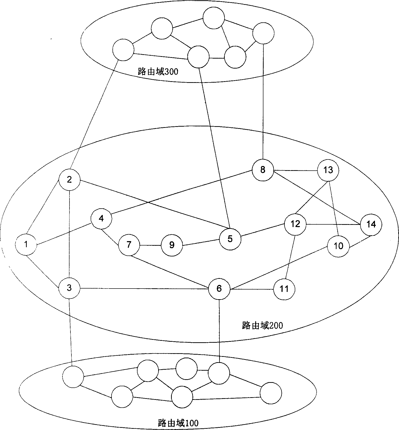
[0024] figure 1 The exemplary optical network consists of three routing domains: routing domain 100 , routing domain 200 and routing domain 300 . Each routing domain belongs to different operators and is managed by different administrators. Each routing domain has a different number of network element devices (referred to as network elements), and the network elements are connected by optical fibers. 16 channels of wavelength division multiplexing optical signals are transmitted in the optical fiber. Each network element is embedded with Open Shortest Path First (OSPF) routing protocol, Resource Reservation with Traffic Engineering (RSVP-TE) signaling protocol, and Link Management (LMP) protocol. figure 1 A small circle in represents a network element, and each network element is numbered in the routing domain 200 for the convenience of the following description.

...


PUM


Abstract

The method includes following steps: (1) borderline net elements in optical network route domain generate current network topology of this route; (2) calculating available information of wavelengths between borderline net elements; (3) constructing a new star type topology of current route; (4) optimizing the said star type topology, and generating final conglomerated topology of current route domain. Advantages are: building up needed message of exchanging routes between different route domain; protecting information inside route domain, enhancing safety of network, reducing size of message inside network, moderating bandwidth of signaling network, and suitable to requirement of dynamic characteristics of optical network in large scale.

Description

technical field [0001] The invention relates to a distributed network topology aggregation method, in particular to a method for summarizing the routing domain and compressing the topology information of the routing domain in an Automatic Switching Optical Network (ASON) based on wavelength routing using a layered routing architecture, belonging to optical networks [0002] technology field. Background technique [0003] The International Telecommunication Union (ITU-T) positions the Automatically Switched Optical Network (ASON / ASTN) as a global unified transport network. It is expected that thousands of switches and millions of terminal nodes will be connected to this network in the future. middle. For such a large-scale network, if all network devices are managed in a single routing domain, it will bring many problems to routing and connection management, such as: a single node needs to maintain an overly large routing table; routing protocols The distribution of topolog...

Claims


Application Information

Patent Timeline
IPC IPC(8): H04B10/27H04L12/28
Inventor 郑小平张锋张汉一
Owner TSINGHUA UNIV
Why Eureka
Try Eureka