Automatic fire extinguishing cannon and its control method

A fire monitor and automatic technology, which is applied in the field of automatic fire-fighting devices, can solve problems such as inability to implement automatic operation, delayed fire extinguishing, and inability to automatically align with the ignition point.

Active Publication Date: 2005-04-06
HEFEI KDLIAN SAFETY TECHNOLOGY CO LTD
View PDF1 Cites 26 Cited by
  • Summary
  • Abstract
  • Description
  • Claims
  • Application Information

AI Technical Summary

Problems solved by technology

[0002] According to "Optical Technology" (May 2003, Vol. 29, No. 3, pp. 292-294) "Fire Spatial Positioning Method Based on CCD Image" and "Dayang Information Network" (http://www.dayoo.com, 2001 April 14) Comprehensive report on "I am world-leading in large space fire research": Existing fire monitors do not have the functions of automatic flame identification, automatic positioning and remote communication. After the device is discovered, the manual start button is used to spray water to extinguish the fire. After the fire is extinguished, it is also necessary to manually control the fire water monitor to stop running. This will inevitably delay the best time to extinguish the fire and cause secondary water damage, especially in Unattended tall spaces and areas that require key protection, especially require the installation of automatic fire cannons; The article "Summary of Water Supply Design Demonstration" reported: "The development of fire-fighting water cannon products began in the 1990s in China. One of the key topics of the "Ninth Five-Year Plan" of the Shanghai Fire Research Institute was "development of fire-f...

Method used


Image

  • Automatic fire extinguishing cannon and its control method
  • Automatic fire extinguishing cannon and its control method
  • Automatic fire extinguishing cannon and its control method

Examples


Embodiment 1

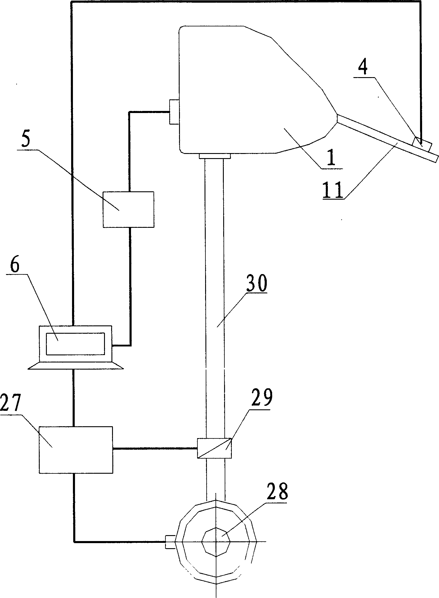
[0035] The automatic fire monitor of the present invention is composed of a cannon body 1 and a control system 2; wherein the control system 2 is composed of a water supply device 3, a flame image locator 4, a decoder 5 and a computer 6.

[0036] The mechanical structure of automatic fire monitor gun body 1 is as follows in the present embodiment:

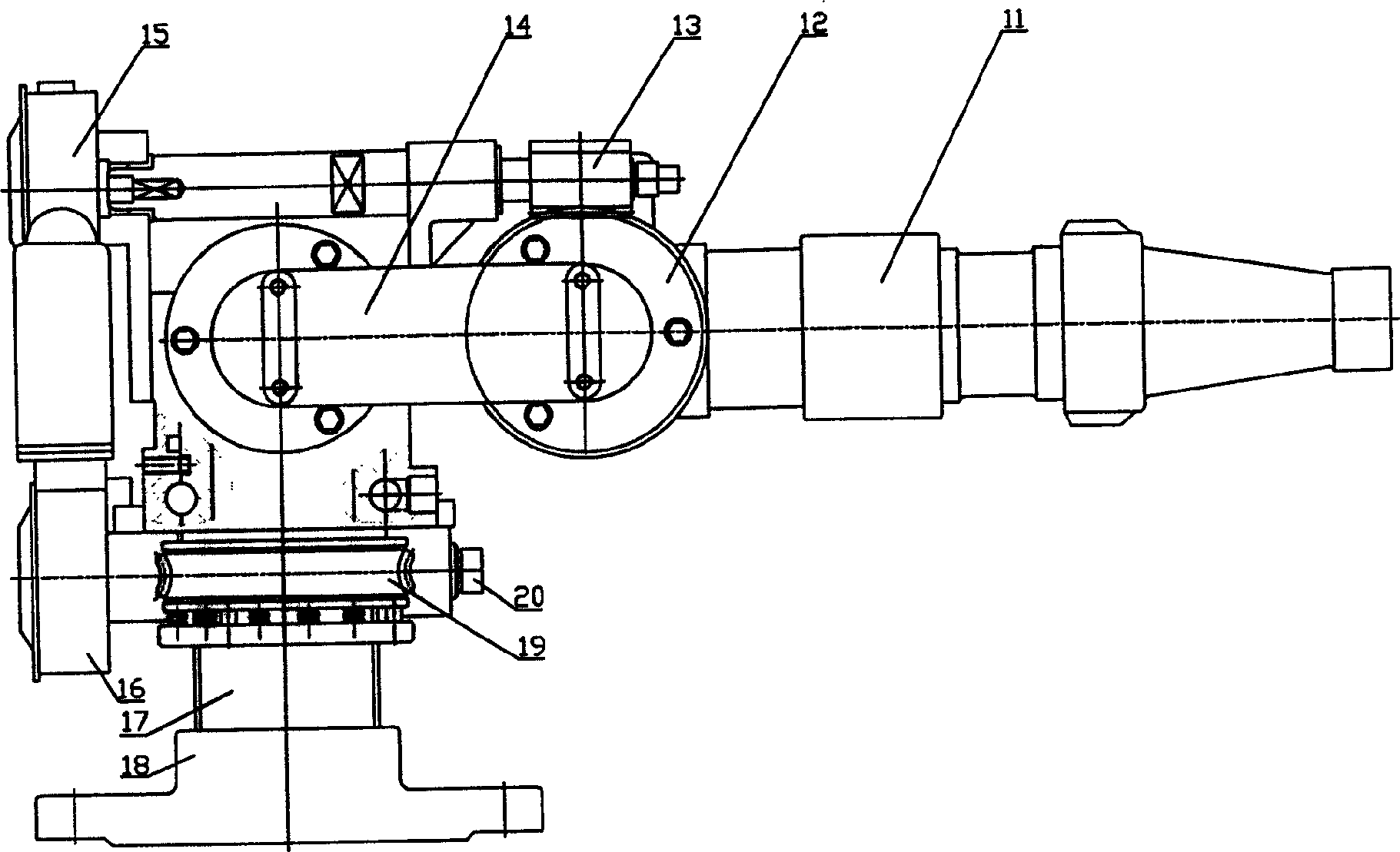
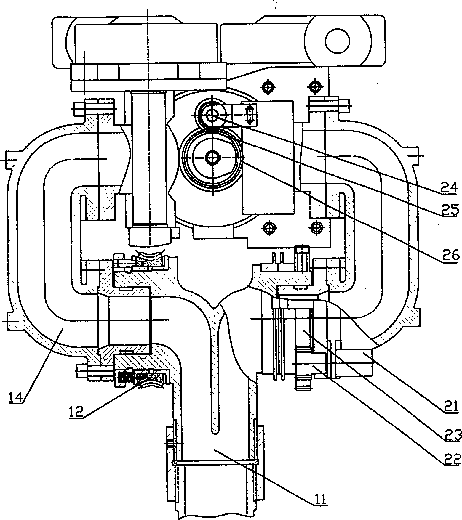
[0037] The nozzle 11 is composed of the left inlet branch pipe and the right inlet branch pipe connected to the outlet branch pipe; the main cavity 14 is a cavity composed of a cylinder and two branch pipes on the upper part, and these two branch pipes are respectively connected to the left and right inlets of the nozzle The branch pipes are connected; the upper end of the pipe body 17 is placed in the cylinder of the main cavity 14, the lower end of the pipe body 17 is fixed on the flange 18, and is connected to the water inlet pipe 30 by the flange 18;

[0038] The worm gear 12 installed at the connection between the right inlet ...


PUM


Abstract

The invention automatic fire artillery and its control method, is composed by the artillery body and the control system, its characteristic is the system is composed by the water supply installment, the flame picture locator, the decoding as well as the computer; The computer control artillery body movement, accepts the fire alarm through the hypothesis procedure, gains the artillery body position and the flame picture information through the angle potentiometer and the flame picture locator, promptly adjusts the artillery body position and the nozzle angle, after aims the artillery body nozzle at the flame surface vanguard, automatically turns on the water pump and the motorized valve,sprays water to the fire point,fights the fire, until the flame extinguishes, this road alarm has already eliminated.The invention automatic fire artillery can linkage with the fire prevention alarm system,the computer automatic control fire prevention artillery to carry on the flame recognition in spatial scope of the hypothesis monitoring, the flame space localization and automatically open the valve spraying of water, suppresses the flame, specially suits to the big space and nobody value defends the situation the fire safe monitoring and save goal, may raise the automated level of the early fire saves goal.

Description

Technical field: [0001] The invention belongs to the technical field of fire-fighting equipment, and in particular relates to an automatic fire-fighting device with electromechanical integration for automatic identification of flames, automatic positioning, automatic water spraying and fire extinguishing and remote communication functions. Background technique: [0002] According to "Optical Technology" (May 2003, Vol. 29, No. 3, pp. 292-294) "Fire Spatial Positioning Method Based on CCD Image" and "Dayang Information Network" (http: / / www.dayoo.com, 2001 April 14) Comprehensive report on "I am world-leading in large space fire research": Existing fire monitors do not have the functions of automatic flame identification, automatic positioning and remote communication. After the device is discovered, the manual start button is used to spray water to extinguish the fire. After the fire is extinguished, it is also necessary to manually control the fire water monitor to stop runn...

Claims


Application Information

Patent Timeline
IPC IPC(8): A62C31/02A62C37/00
Inventor 袁宏永疏学明苏国锋梁光华刘申友刘炳海陈涛马云王进军方斌
Owner HEFEI KDLIAN SAFETY TECHNOLOGY CO LTD
Why Eureka
Try Eureka