Microfabricated fluidic structures

A microfluidic and fluid technology, which is applied in fluid controllers, laboratory containers, chemical analysis using microanalysis, etc., can solve problems such as difficult conventional devices to measure fluid volume

Inactive Publication Date: 2005-04-06
IBM CORP
View PDF0 Cites 10 Cited by
  • Summary
  • Abstract
  • Description
  • Claims
  • Application Information

AI Technical Summary

Problems solved by technology

[0007] This technical solution already enables some control over the position of the liquid in the microstructure, but requires the user to deposit the right amount of fluid in the supply port with high precision
[0008] One challenge in moving smaller and smaller amounts of fluid is the difficulty of metering the precise amount of fluid into the supply port using conventional devices

Method used


Image

  • Microfabricated fluidic structures
  • Microfabricated fluidic structures
  • Microfabricated fluidic structures

Examples


Embodiment Construction

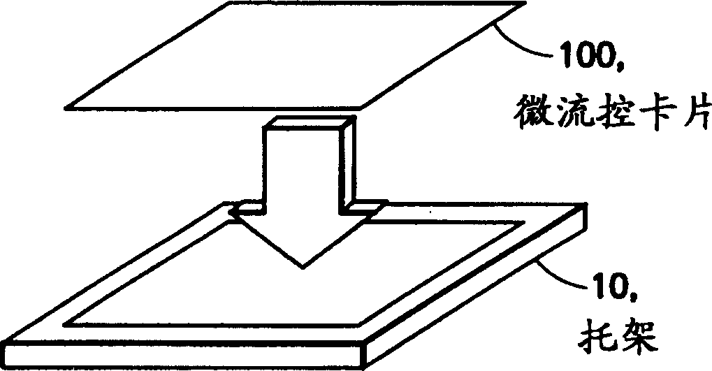
[0035] figure 1 Shows a perspective view of an embodiment of the invention with a bracket / bracket for the embodiment. Card 100 according to the present invention is a relatively thin plate comprising a matrix of fluid containers containing a set of samples to be tested. The overall dimensions of the card 100 and the positions of the modules in the matrix are in compliance with industry standards.

[0036] The card 100 fits into its location in a tray 10 having vacuum and pressure for fluid control and suitable for an automated material handling apparatus.

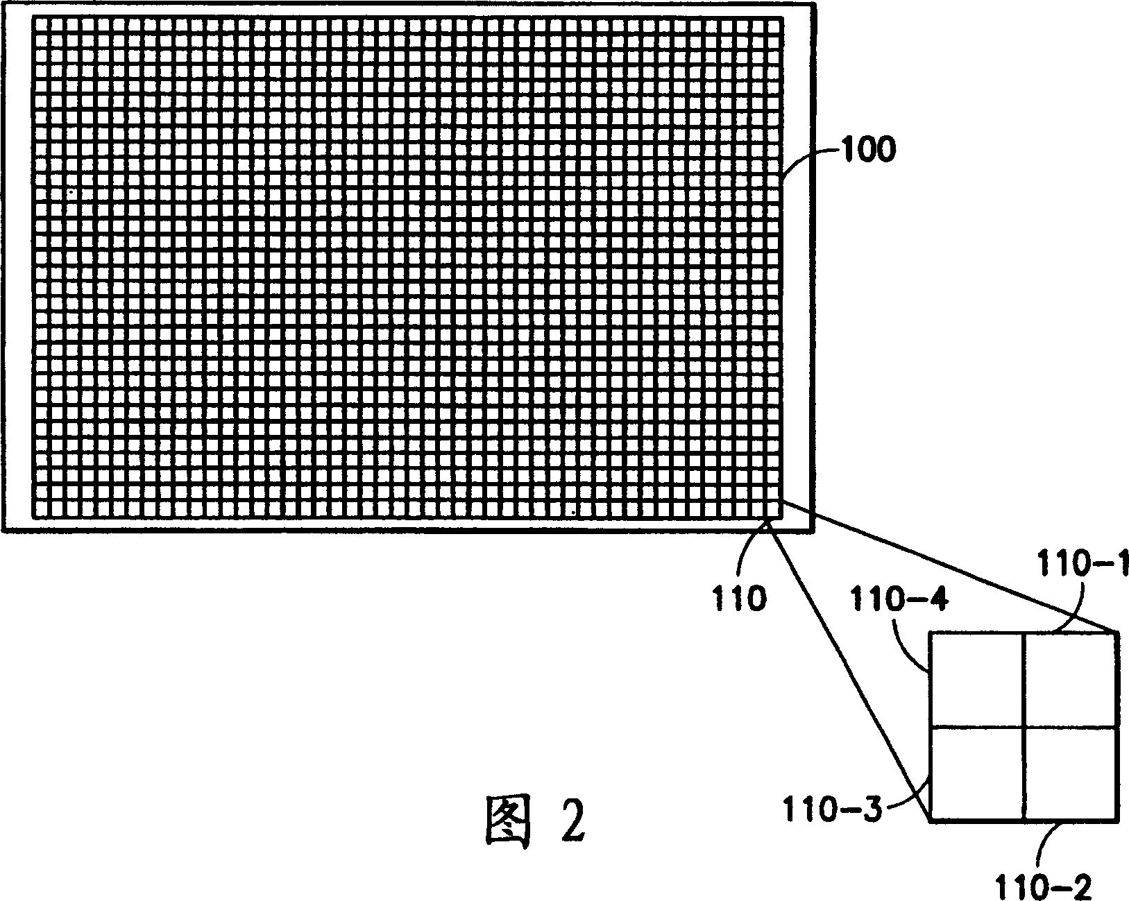
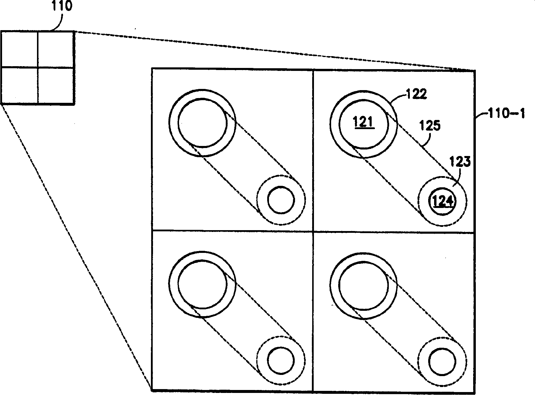
[0037] FIG. 2 shows a top view of a matrix 100 according to the invention. The industry already has established standard matrix specifications, although non-standard matrices can be used if preferred. In this case, the matrix is ​​a group of 48×32 sub-modules, each sub-module includes a 2×2 sub-matrix composed of unit modules. On the lower right side of the figure, a sub-module 110 is shown comprising four unit modules ...


PUM


Abstract

A plate for use in mixing and testing materials in the pharmaceutical industry is formed by a method in which an array of sample cells contain a U-shaped structure having two vertical apertures connected by a horizontal passage in a bottom sheet; reagents are drawn in to the vertical passages by capillary action or other forces and react in the horizontal passage. An optional version of the invention includes a relatively large reservoir for containing rinsing fluids.

Description

[0001] Cross References to Related Applications [0002] This application is related to the invention described in Attorney Docket No. FIS920020186US1, the entirety of which is incorporated herein by reference. technical field [0003] The field of the invention is the simultaneous testing of multiple compounds for biological / chemical interactions. In particular, the present invention is an apparatus / structure and a method for testing drug interactions. Background technique [0004] To increase the efficiency of drug development, leading pharmaceutical companies often utilize high-throughput screening (HTS) technology to evaluate potential drug candidates. During high-throughput screening, test the reaction of a reagent set A (such as a biological target with suitable assay reagents) with a chemical B1-Ban (such as a compound obtained from a molecular library) capacity, where n can be a large number on the order of millions. High-throughput screening enables rapid and sim...

Claims


Application Information

Patent Timeline
Patent Type & Authority Applications(China)
IPC IPC(8): B01L3/00C40B60/14G01N33/53
CPCB01J2219/00364B01L3/50857G01N33/5304B01L2400/0418B01L3/5025B01L2400/0421B01L2300/0819B01J2219/00317B01L2400/0688B01L2400/086B01J2219/00319B01L2400/0406B01L2400/0487B01L2400/0457C40B60/14B01L3/502715
Inventor J·N·胡梅尼克G·纳塔拉詹S·惠利A·杨
Owner IBM CORP
Why Eureka
Try Eureka