Sanitary Utility Hanger System

a technology of utility hangers and hangers, which is applied in the direction of securing devices, sewer systems, sewage draining, etc., can solve the problems of time-consuming and laborious procedures, long construction time, and high cost of custom fabrication, and achieve the effect of convenient installation and reus

Inactive Publication Date: 2016-11-10
MADISON SHEET METAL LLC
View PDF3 Cites 25 Cited by
  • Summary
  • Abstract
  • Description
  • Claims
  • Application Information

AI Technical Summary

Benefits of technology

[0008]The invention is a sanitary utility hanger system that replaces the conventional UNISTRUT and custom made hangers in the food and beverage industry. The hanger system may support pipes, sanitary tubing, electrical conduits, fans, heaters and anything that can be mounted to a stand-off. The elements of the hanger system working together comprise an effective sanitary hanger system. The cooperation of the system elements facilitates ready installation and reuse of parts. The main hanger has a unit hole and slot design which allows the main hanger to be simply cut to the needed length and installed using solid round rod which is field threaded at the ends. The rods extend from the roof or ceiling to the main hanger unit. The main hanger supports the various utility standoffs. Additionally, the main hanger can be used to support other equipment that hangs off the ceiling. The standoffs and connected pipes and conduits can extend above or below the main hanger. The main hanger is preferably a stainless steel section with a semicylindrical central segment which is terminated by first and second planar wings on opposite sides of the central segment. Where greater load carrying capacity is required, e.g., stiffness, the main hangers may be fabricated to have wings of greater length.

Problems solved by technology

Harborage points in particular must be attended to, which can be a very time consuming and hand-labor-intensive procedure.
However, such custom fabrication is costly and can take a long time to construct.
Other hangers for these environments must be custom ordered to length, which takes extra time and money to pre-layout all the hangers involved.
However, u-bolt and nut systems can present harborage points which are difficult to clean.
Other systems use angled cross members supported by threaded rods, but these require specialized and costly fasteners.
Other hangers can only be fabricated and installed by specialty personnel that know how to fabricate and weld.

Method used


Image

  • Sanitary Utility Hanger System
  • Sanitary Utility Hanger System
  • Sanitary Utility Hanger System

Examples


Embodiment Construction

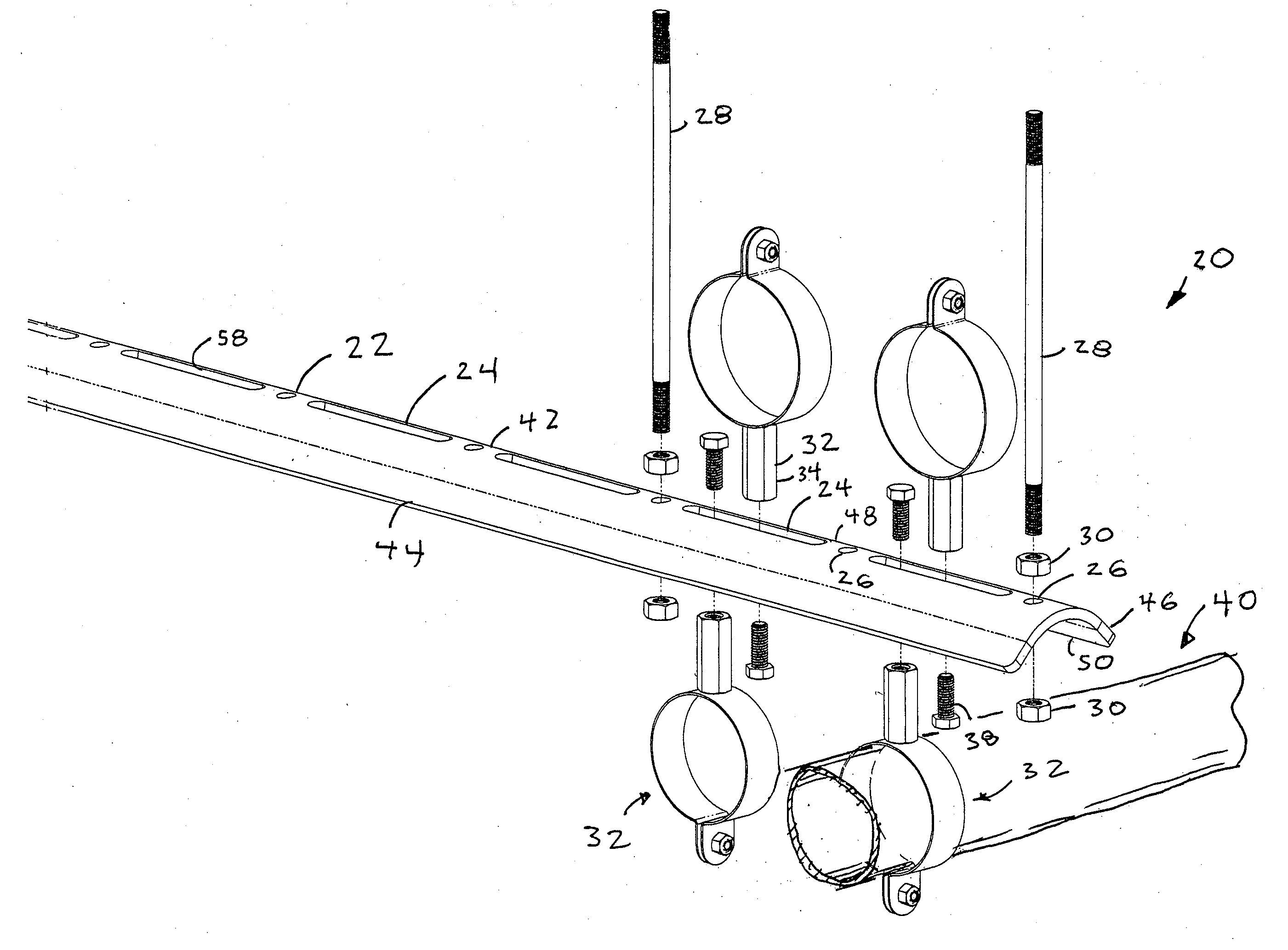
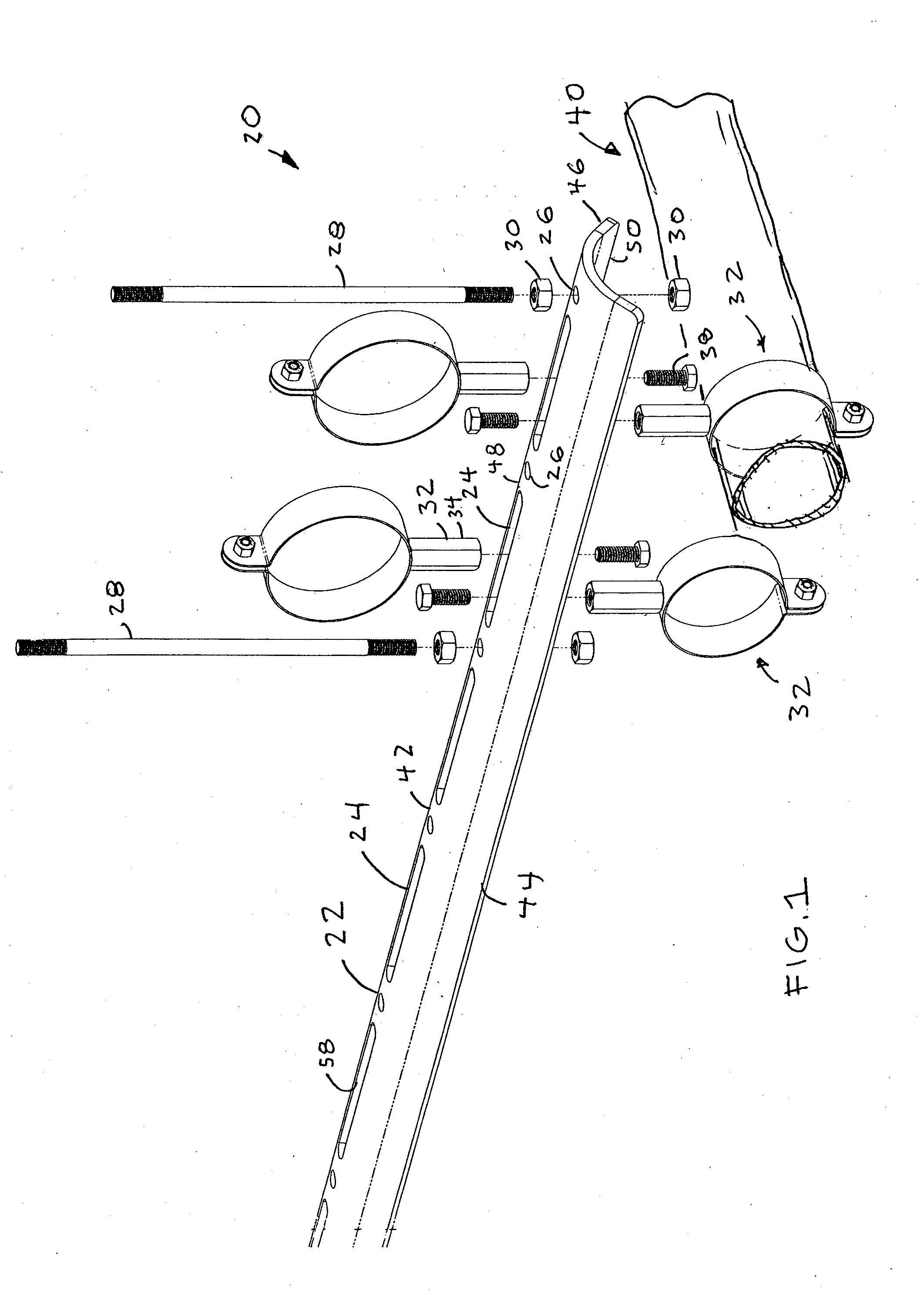
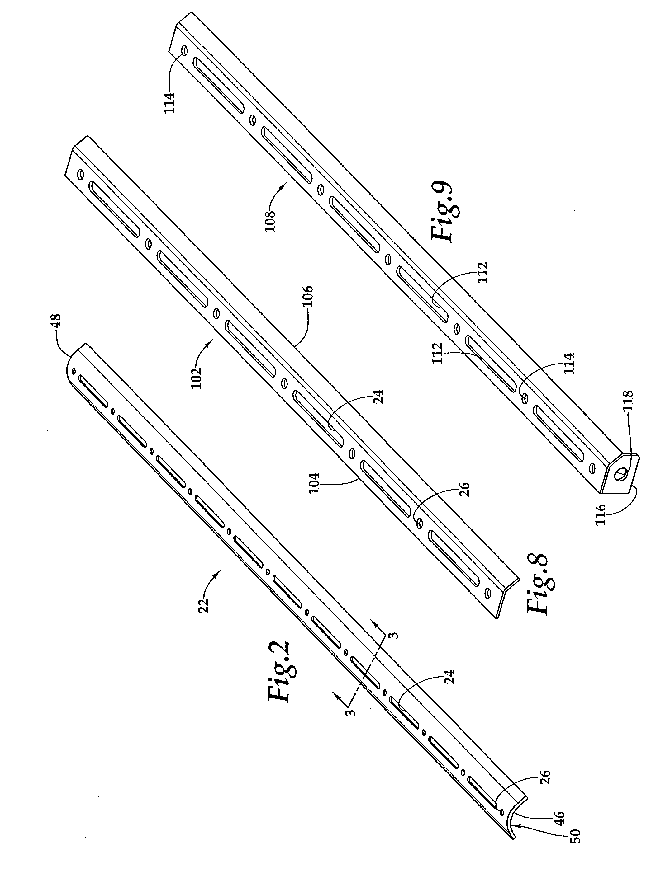
[0026]Referring more particularly to FIGS. 1-10, wherein like numbers refer to similar parts, a sanitary hanger system 20 is shown in FIG. 1. The system includes a main hanger 22 which has an array of axial slots 24 positioned between mounting holes 26 aligned on the axis. The slots 24 may be about ½ inch wide, with ½ inch radius rounded ends. The slots are about four inches between the centers of the rounded slot ends, and the mounting holes are about ½ inch in diameter with the centers between mounting holes being spaced about six inches apart. Conventional round rod 28 is threaded on its two ends, allowing it to be bolted to the ceiling on one end, and fixed to the main hanger 22 by conventional nuts 30 on both sides of the hanger. The main hangers 22 may be provided in 68 inch lengths for optimal usage with conventional bar joist centerlines. The distance between the outermost mounting holes 26 is 66 inches which corresponds to standard joist spacing. The main hangers 22 may be ...


PUM


Abstract

A utility hanger system for the food, beverage, and pharmaceutical industries has a main hanger member extending in an axial direction, which has an axially extending semicylindrical central segment of a first radius, the central segment terminating in first and second wings on opposite sides of the central segment. A slot extends axially along the main hanger member and is positioned between two rod holes. Rods extend through the rod holes to an overhead support member and are fixed to the main hanger member by nuts. Pipes and conduits are gripped within standoffs which space the pipes from the main hanger member with a hexagonal member which is bolted within the main hanger member slot. The pipes and conduits can be supported above or below the main hanger member.

Description

CROSS REFERENCES TO RELATED APPLICATIONS[0001]The present application claims the benefit of priority of U.S. provisional App. No. 62 / 158,278, filed May 7, 2015, the disclosure of which is incorporated by reference herein.STATEMENT AS TO RIGHTS TO INVENTIONS MADE UNDER FEDERALLY SPONSORED RESEARCH AND DEVELOPMENT[0002]Not applicable.BACKGROUND OF THE INVENTION[0003]The present invention relates to arrangements for supporting utility pipes and conduits in general, and in particular those for use within food or drug processing facilities where high levels of hygiene must be maintained.[0004]Production facilities which produce products for human consumption such as food, beverages, and pharmaceuticals, must be maintained in a sanitary condition to avoid contamination of the products which might be harmful to consumers. Just as with any manufacturing site, these facilities include conventional conduits and piping for delivering water, electricity and ventilation. Moreover, there are freq...

Claims


Application Information

Patent Timeline
Patent Type & Authority Applications(United States)
IPC IPC(8): F16L3/22F16L3/133
CPCF16L3/133F16L3/221F16L3/13F16L3/26F16L3/243E03F1/00F16B1/00
Inventor BROWN, MATTHEW E.
Owner MADISON SHEET METAL LLC
Why Eureka
Try Eureka