Supercharge Your Innovation With Domain-Expert AI Agents!

Optical waveguide module

一种光波导路、平面光波导的技术,应用在光波导光导、光导、光波导的耦合等方向,能够解决不能够正确地监视信号光光强度等问题,达到构成和制造步骤简单化的效果

Inactive Publication Date: 2005-04-27
SUMITOMO ELECTRIC IND LTD
View PDF0 Cites 0 Cited by
  • Summary
  • Abstract
  • Description
  • Claims
  • Application Information

AI Technical Summary

Problems solved by technology

In this case, if the polarization state of the signal light propagating along the optical waveguide is specified, the light intensity of the signal light cannot be correctly monitored

Method used


Image

  • Optical waveguide module
  • Optical waveguide module
  • Optical waveguide module

Examples


Embodiment Construction

[0031] Next, we describe in detail preferred embodiments of the optical waveguide module according to the present invention together with the accompanying drawings. In addition, in the description of the drawings, the same reference numerals are attached to the same elements, and overlapping descriptions are omitted. In addition, scale ratios in the drawings do not necessarily match those in the description.

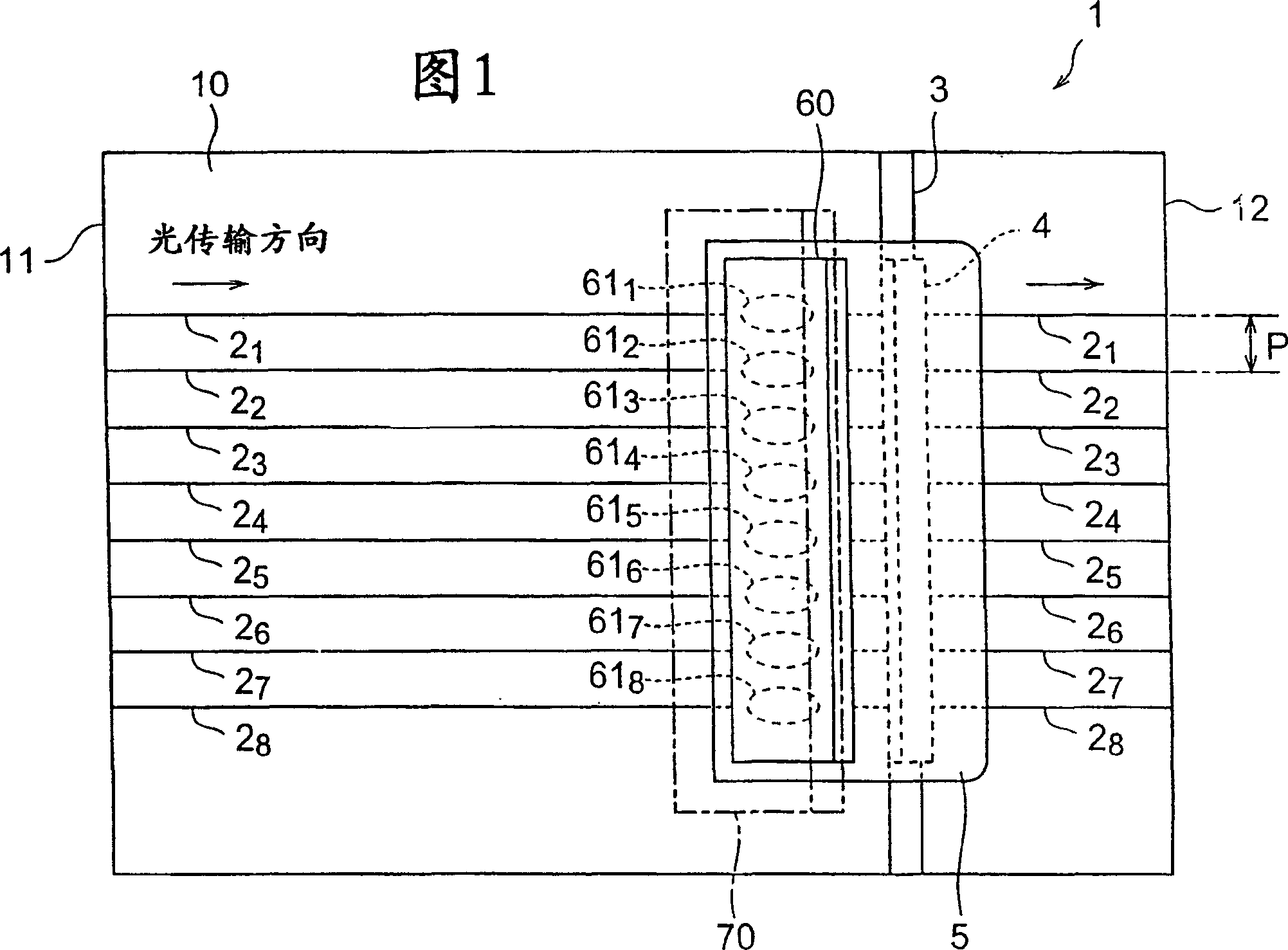
[0032] FIG. 1 is a plan view showing the configuration of a first embodiment of an optical waveguide module according to the present invention. This optical waveguide module includes a substrate 10 and eight (eight channels) optical waveguides 2 provided on the substrate 10. 1 ~2 8 Constitute the light path 1. In this embodiment, as the optical waveguide 2 1 ~2 8 , a planar waveguide type optical waveguide formed on the substrate 10 can be used.

[0033] Along the predetermined optical transmission direction (arrow direction in FIG. 1 ), from the input end 11 of th...


PUM


Abstract

A reflection filter (4) is installed on the inner side of a slant groove (3) formed so as to cross an optical waveguide (2n) in a flat waveguide type optical circuit (1). Light reflected off the reflection filter (4) is detected by the optical detector (61n) of an optical detector array (60) to monitor the light intensity of a signal light. A sub-mount substrate (70) is installed on the upper surface side of the optical circuit (1) in association with the optical detector (61n), and the optical detector array (60) is held by an optical detector mounting surface (71) tilted at an angle alpha (0 DEG < alpha < 90 DEG ) with respect to the top surface of the optical circuit (1) so that reflection light from the reflection filter (4) is incident onto the light incident surface (63) of the optical detector (61n) of the optical detector array (60) at a specified angle [Phi]. Whereby, it is possible to implement an optical waveguide module capable of monitoring a light intensity correctly regardless of the polarization condition of a signal light.

Description

technical field [0001] The present invention relates to an optical waveguide module having an optical waveguide provided on a substrate. Background technique [0002] In an optical path using an optical waveguide such as an optical fiber or a planar optical waveguide, it may be desirable to keep the light intensity of the signal light propagating along each optical waveguide constant and to control the light intensity of the signal light to an appropriate value. In this case, the light intensity of the signal light is monitored in the optical path, or further, the light intensity is controlled according to the result of the monitoring. [0003] In the monitor of the light intensity of the above-mentioned signal light, a method of separating a part of the signal light by providing an optical coupler on the optical waveguide has been used so far. In this method, by setting an optical coupler at a predetermined position on the optical waveguide to separate about a few percent ...

Claims


Application Information

Patent Timeline
Patent Type & Authority Applications(China)
IPC IPC(8): G02B6/12G02B6/36G02B6/42
CPCG02B6/42G02B6/4212G02B6/3652G02B6/4246G02B2006/12104G02B6/4214G02B6/3636G02B6/4249G02B2006/12109G02B6/43
Inventor 小宫健雄佐佐木隆藤村康胜山造山林直之
Owner SUMITOMO ELECTRIC IND LTD
Features
  • R&D
  • Intellectual Property
  • Life Sciences
  • Materials
  • Tech Scout
  • Unparalleled Data Quality
  • Higher Quality Content
  • 60% Fewer Hallucinations
Learn More