Eureka AIR delivers breakthrough ideas for toughest innovation challenges, trusted by R&D personnel around the world.

Suction nozzle structure for vacuum cleaner

A vacuum cleaner and suction port technology, applied in the direction of the suction nozzle, etc., can solve the problems of reduced cleaning efficiency, small absorption area, and reduced cleanliness, and achieve the effects of increasing the suction area, improving performance, and improving efficiency

Inactive Publication Date: 2005-05-04
LG ELECTRONICS (TIANJIN) APPLIANCES CO LTD
View PDF0 Cites 32 Cited by
  • Summary
  • Abstract
  • Description
  • Claims
  • Application Information

AI Technical Summary

Problems solved by technology

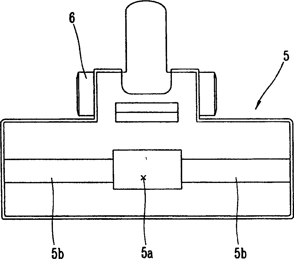
[0007] However, in the existing suction nozzle structure, the suction channels 5b and 5b that constitute the absorption area are in a linear structure, which not only makes the entire absorption area too small, but also the air flow of the suction channels 5b and 5b on both sides is generated at the suction port 5a. conflict with each other, resulting in loss of flow
[0008] Moreover, only a strong vacuum phenomenon is generated around the suction port 5a and the suction passage 5b, 5b, while other parts cannot be closely attached to the surface to be cleaned, thus reducing the cleanability
There is no structure in the cleaning surface to attract particles such as fine sand, thus reducing the cleaning efficiency

Method used


Image

  • Suction nozzle structure for vacuum cleaner
  • Suction nozzle structure for vacuum cleaner
  • Suction nozzle structure for vacuum cleaner

Examples


Embodiment Construction

[0025] Hereinafter, the nozzle structure of the vacuum cleaner of the present invention will be described in detail with reference to the drawings and embodiments.

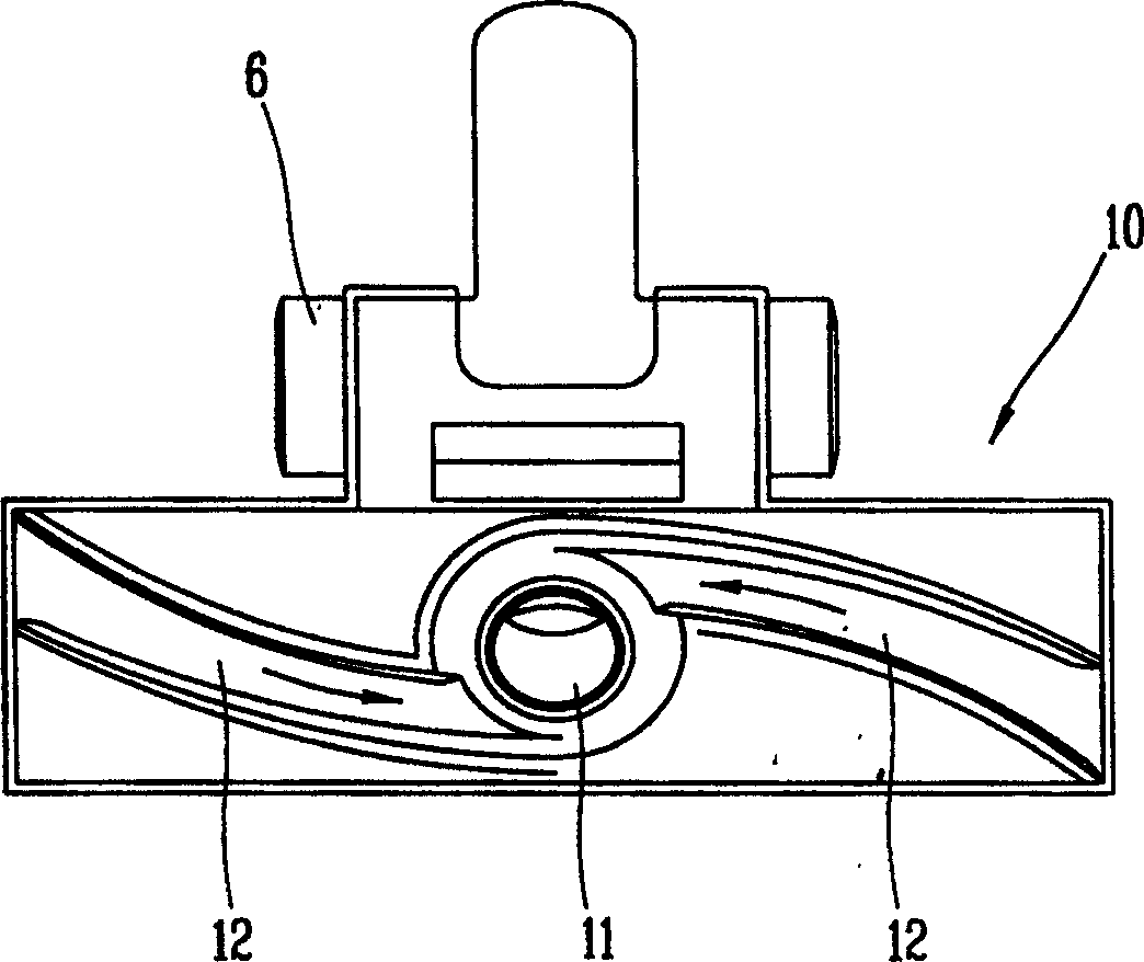
[0026] Figure 3 to Figure 9 It is a bottom view of exemplary examples of the vacuum cleaner nozzle designed in the present invention, Picture 10 It is a bottom view of another embodiment of the vacuum cleaner nozzle designed in the present invention, Picture 11 It is a longitudinal section view of another embodiment of the suction nozzle of the vacuum cleaner designed in the present invention.

[0027] As shown in the figure, the suction nozzle 10 of the vacuum cleaner designed in the present invention includes: set at the center of its bottom surface, such as figure 1 As shown, the suction port 11 communicated with the main body 1 through the extension pipe and the suction hose 2 is constituted by suction passages 12, 12 which are recessed to a certain depth on the bottom surface of the suction nozzle 10 and com...


PUM


Abstract

The present invention provides a floor nozzle structure of dust cleaner. Its structure comprises a suction inlet placed on the undersurface of floor nozzle and used for sucking refuse and a suction channel which is connected with suction inlet for guiding the refuse to suction inlet and is recessed to a certain depth, the plane projection of the described suction channel is characterized by setting at least more than two suction channels whose suction direction is tangential to the suction inlet. Besides, said invention also provides two other floor nozzle structures, their common feature lies in that these floor nozzle structures can greatly raise the suction force for sucking air so as to raise the performance of dust cleaner.

Description

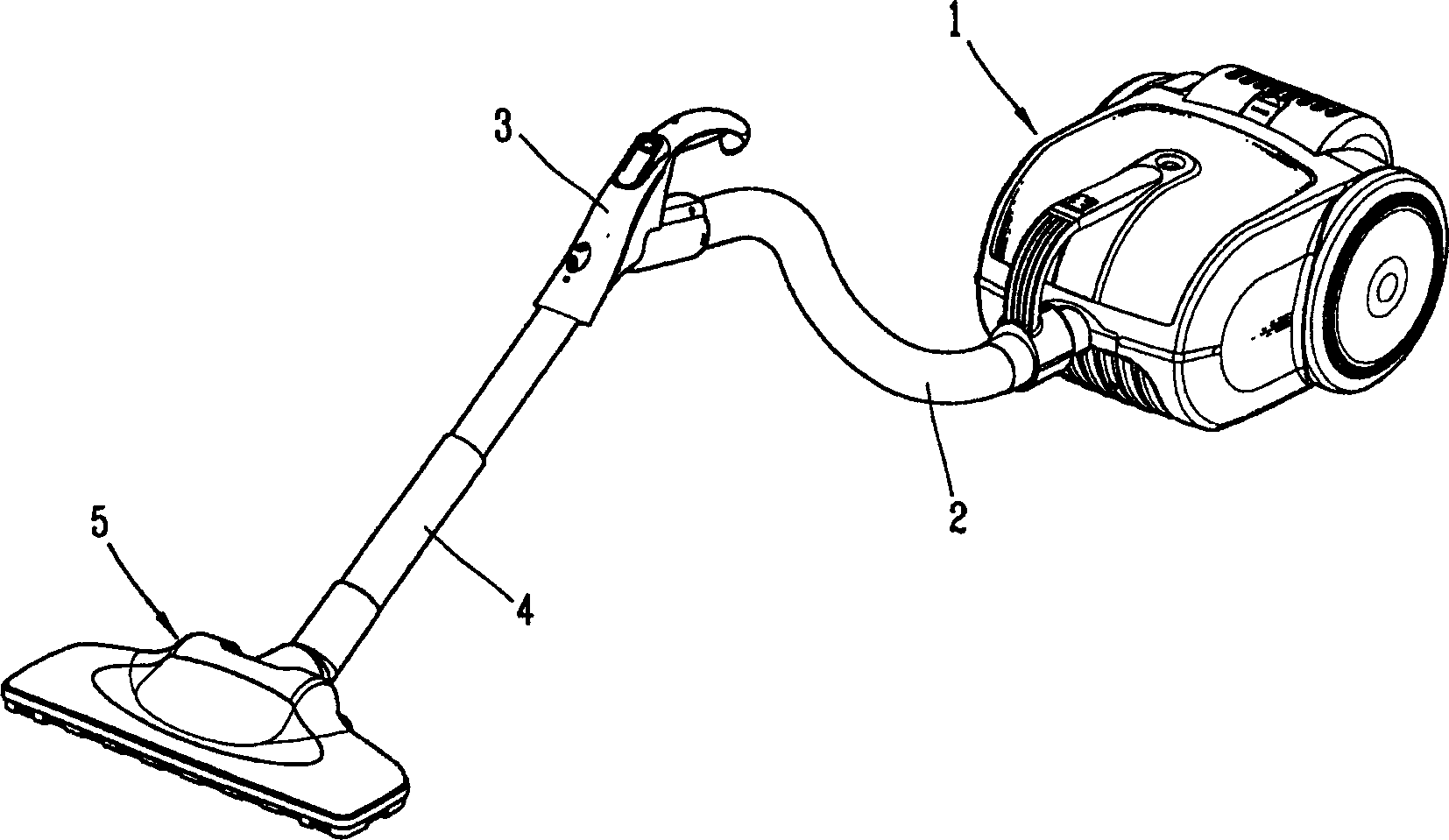
Technical field [0001] The present invention relates to a suction nozzle structure of a vacuum cleaner, and particularly relates to a suction nozzle structure of a vacuum cleaner that improves the shape and position of the suction channel and the suction port to improve the performance of the vacuum cleaner. Background technique [0002] Generally, vacuum cleaners such as figure 1 As shown, it includes: a fuselage with a suction fan that generates suction force 1, an inhalation hose connected to the front of the fuselage 1 and sending out foreign objects sucked from the bottom surface 2, connected to the other end of the suction hose 2 with The user can select the handle 3 of the selection key of the cleaning mode, the extension tube 4 connected to the other end of the handle 3, and the suction nozzle 5 connected to the end of the extension tube 4 to suck foreign matter on the surface to be cleaned. [0003] Nozzle 5 as figure 2 As shown, a suction port 5a is provided in the ce...

Claims


Application Information

Patent Timeline
Patent Type & Authority Applications(China)
IPC IPC(8): A47L9/02
Inventor 赵炯株柳正煥郑京仙
Owner LG ELECTRONICS (TIANJIN) APPLIANCES CO LTD
Why Eureka
Eureka Blog
Learn More