Controllable flux permament magnetic synchronous motor of built-in mixed rotor magnetic path structure

A permanent magnet synchronous motor and hybrid technology, applied in the direction of magnetic circuit shape/style/structure, magnetic circuit rotating parts, etc., can solve the problems of inverter power device damage, loss of magnetic field weakening control ability, decline, etc., to achieve the best results significant effect

Inactive Publication Date: 2005-05-18
TIANJIN UNIV
View PDF0 Cites 14 Cited by
  • Summary
  • Abstract
  • Description
  • Claims
  • Application Information

AI Technical Summary

Problems solved by technology

In field-weakening speed regulation, if the total stator current is limited, then the quadrature axis current vector i q The resulting torque that can be utilized will decrease; at the same time, due to the direct axis current vector i d To exist all the time, additional copper loss will be generated in the stator three-phase winding
As for the frequency converter, if the inverter fails and the magnetic field weakening control capability is lost, the permanent magnetic field of the rotor rotating at high speed will induce excessive voltage in the motor winding, which may cause damage to the power device of the frequency converter

Method used


Image

  • Controllable flux permament magnetic synchronous motor of built-in mixed rotor magnetic path structure
  • Controllable flux permament magnetic synchronous motor of built-in mixed rotor magnetic path structure
  • Controllable flux permament magnetic synchronous motor of built-in mixed rotor magnetic path structure

Examples


Embodiment Construction

[0011] The specific embodiments of the present invention will be described below with reference to the accompanying drawings:

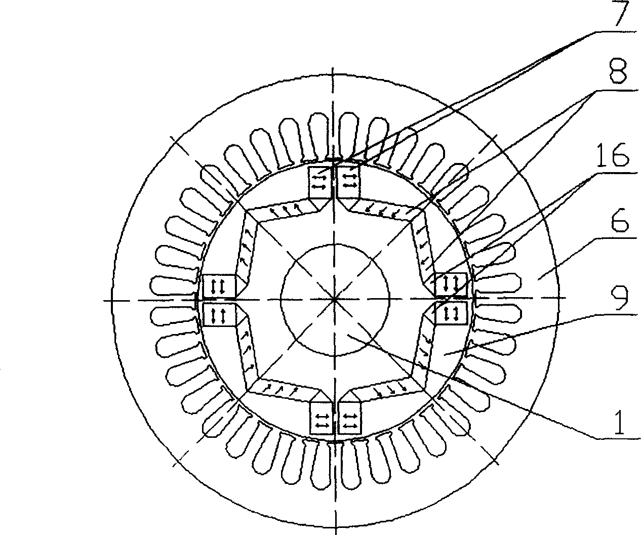
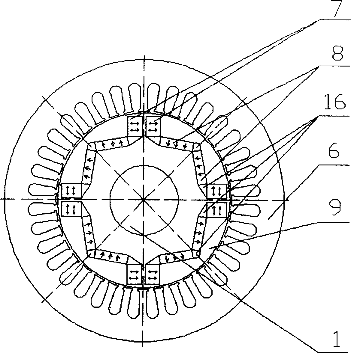
[0012] figure 2 versus image 3 The difference between the two is that the shape of the neodymium iron boron permanent magnets 8 placed radially and their magnetizing directions are different, and the other aspects are completely the same. The specific implementation is also exactly the same. The whole motor is implemented according to the following instructions.

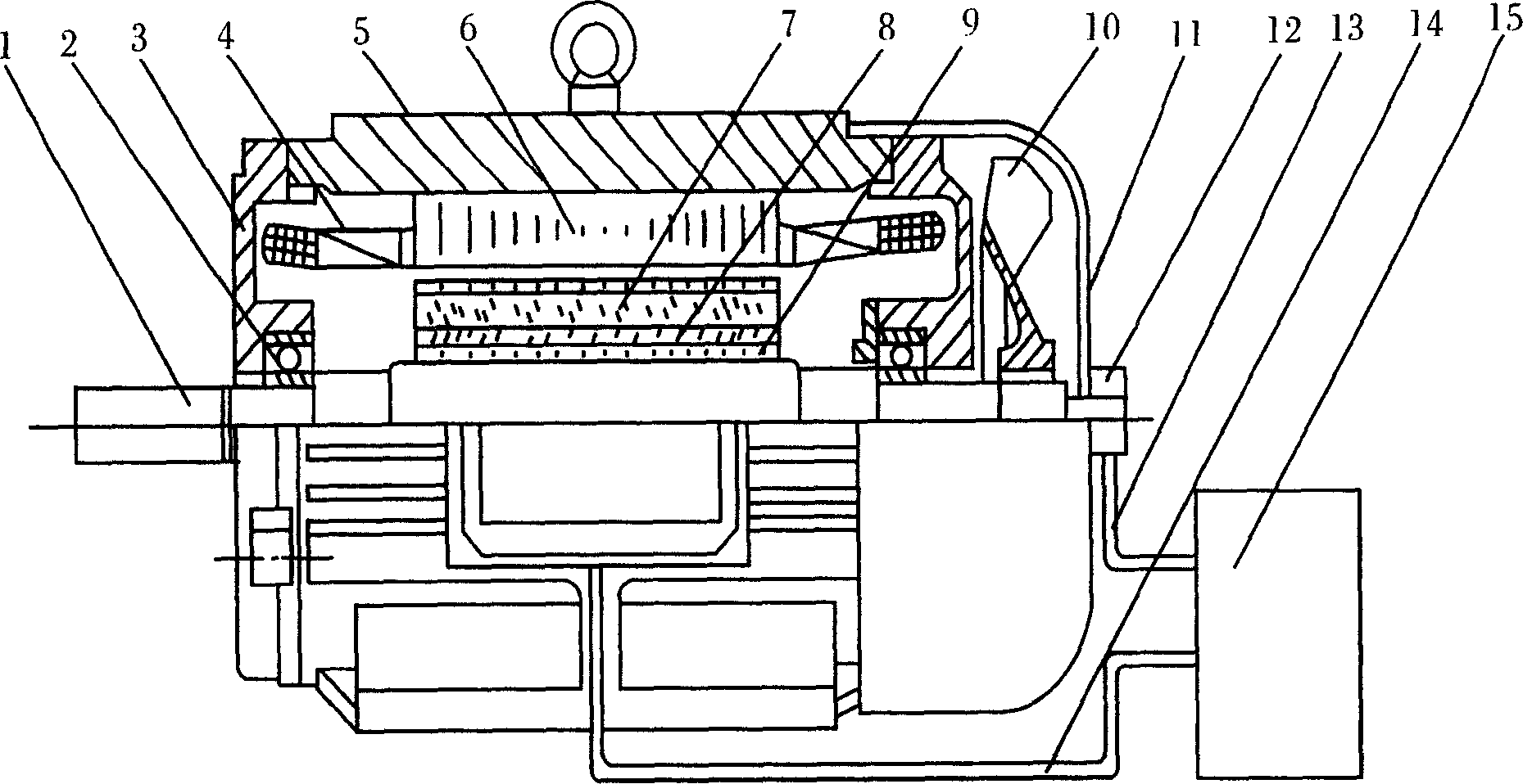
[0013] As mentioned above, the magnetic flux controllable magnetic flux permanent magnet synchronous motor with a built-in hybrid rotor magnetic circuit structure of the present invention is a memory motor. Except for the motor rotor, other parts of the motor are basically the same as the traditional permanent magnet synchronous motor. In other words, the motor end cover 3, frame 5, air-conditioning fan 10, wind cover 11, stator core 6, three-phase stator winding 4 winding, insulation, wire e...


PUM


Abstract

This invention provides a controlled flux magnet synchronous motor of integral hybrid rotor magnetic-circuit structure including a motor splindle, a stator winding, a rotor iron core, a AlNiCo magnet, NdFeB magnet and a rotor iron core, in the rotor iron core, the magnets are place in W shape, AlNiCo is set tangentially and the NdFeB is set in radial position which can be a parallelogram or a rectangle considering the limit of the rotor space. The advantage is that an ampltude controlled d-axis vector is applied to alter the magnetization intensity of the rotor magnet and memerizes the altered flux density.

Description

Technical field [0001] The invention belongs to motor and electric drive control, and specifically relates to a permanent magnet synchronous motor with a built-in hybrid rotor structure magnetic circuit and magnetic flux controllable. Background technique [0002] Generally, in the design of the rotor magnetic circuit and the determination of the size of the permanent magnet in the traditional permanent magnet synchronous motor, it should be considered that the permanent magnet should be prevented from being demagnetized even in the most extreme conditions. This means that at the highest operating temperature, the thickness of the permanent magnet in the traditional permanent magnet motor is large enough to make the demagnetization magnetomotive force generated by the armature reaction lower than the coercive force of the permanent magnet. This is because in traditional permanent magnet motors, especially rare earth permanent magnet motors, once the pe...

Claims


Application Information

Patent Timeline
Patent Type & Authority Applications(China)
IPC IPC(8): H02K1/27
Inventor 陈益广沈勇环王晓远
Owner TIANJIN UNIV
Why Eureka
Try Eureka