
Planetary gear hydraulic speed changing system

A planetary gear system, hydraulic transmission technology, applied in the direction of belt/chain/gear, fluid transmission device, mechanical equipment, etc.

Inactive Publication Date: 2005-05-25
LANZHOU UNIVERSITY OF TECHNOLOGY
View PDF0 Cites 5 Cited by
  • Summary
  • Abstract
  • Description
  • Claims
  • Application Information

AI Technical Summary

Problems solved by technology

Its disadvantage is that it cannot flexibly change speed according to different working conditions

Method used


Image

  • Planetary gear hydraulic speed changing system
  • Planetary gear hydraulic speed changing system
  • Planetary gear hydraulic speed changing system

Examples


Embodiment Construction

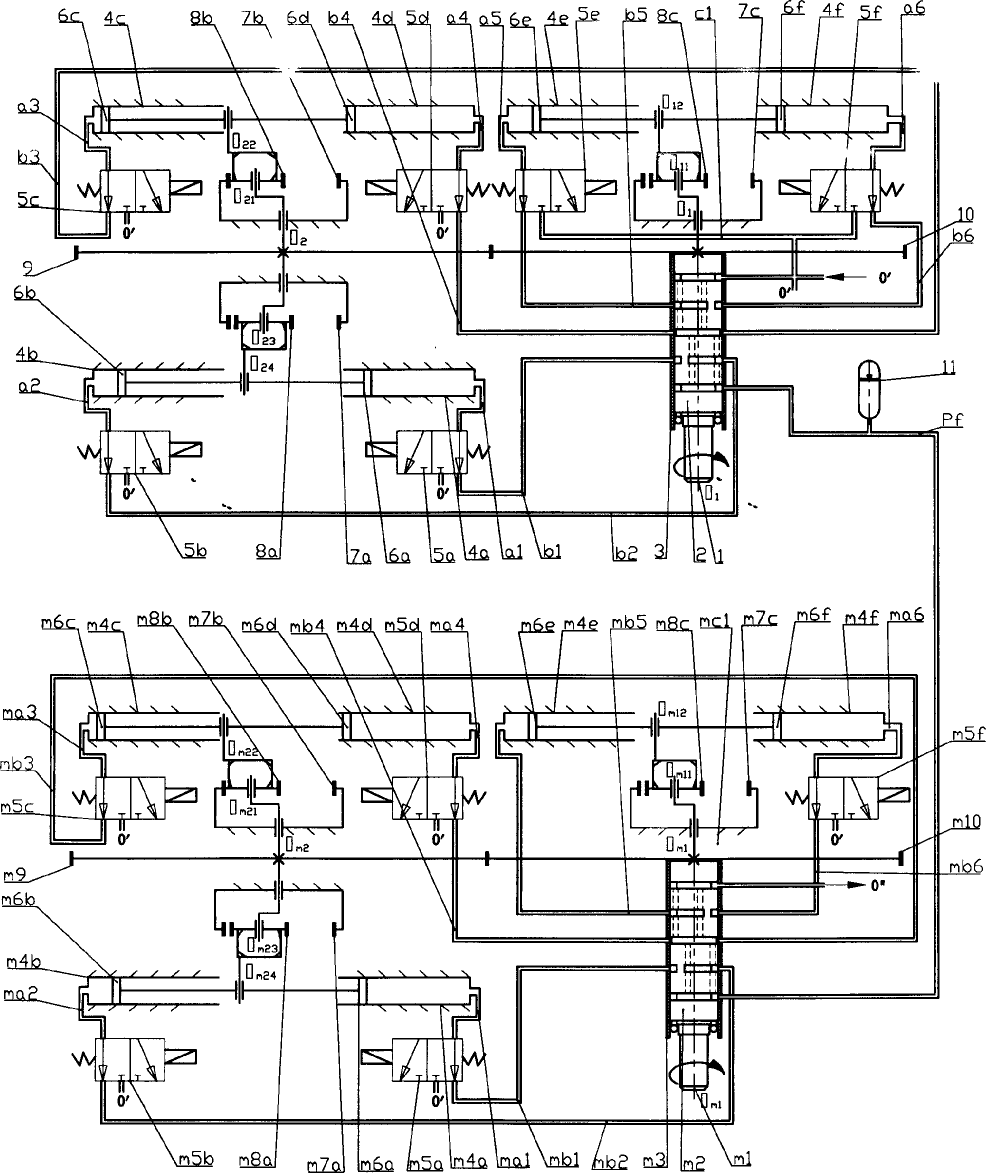
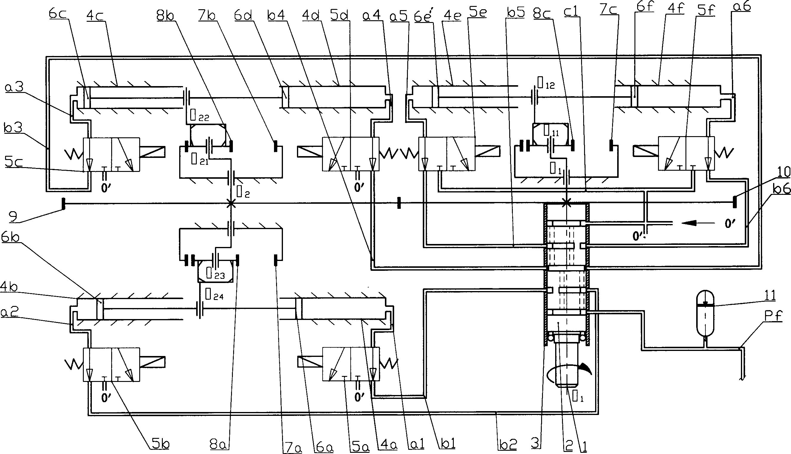
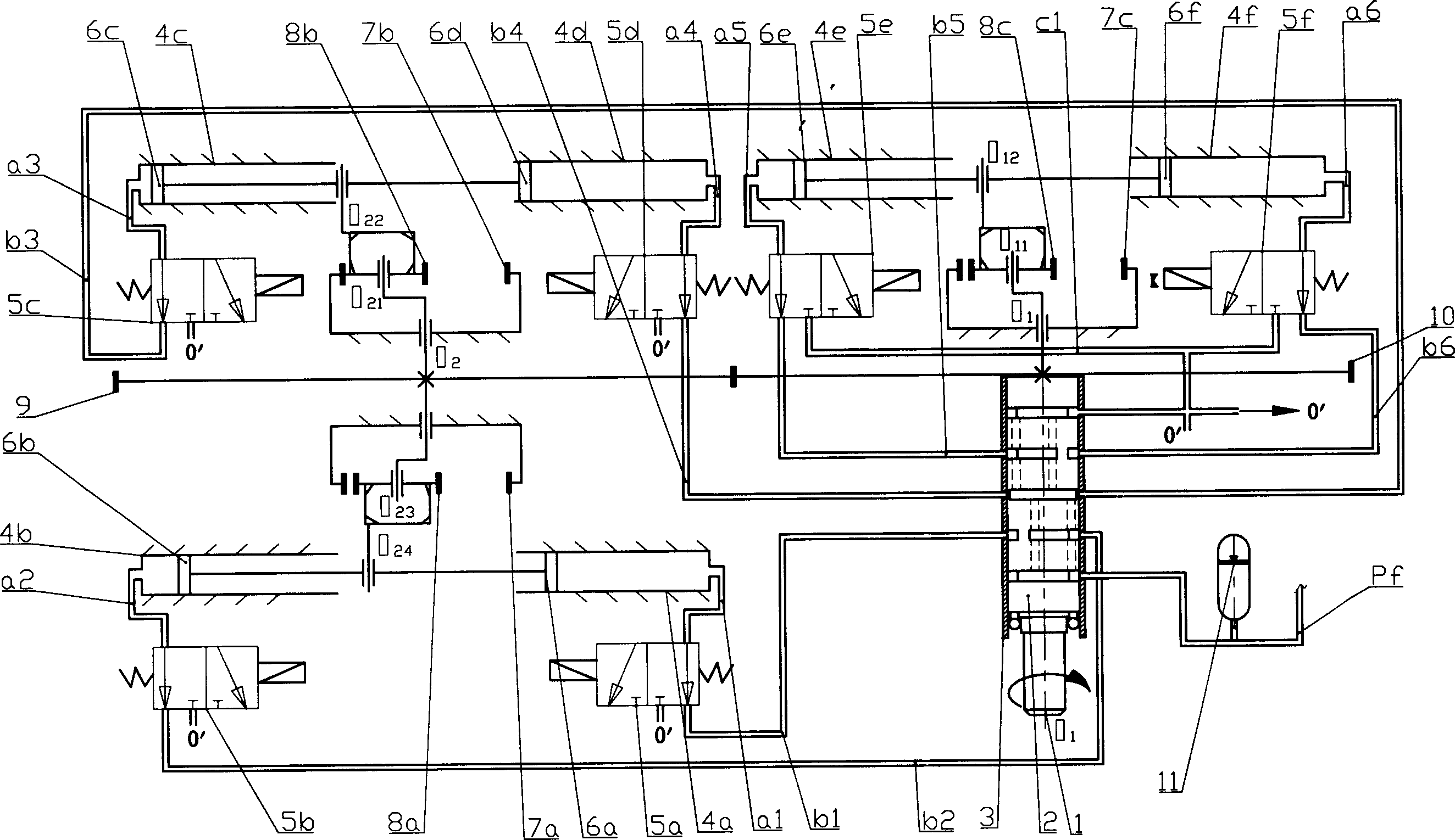
[0009] Such as figure 1 Shown is a schematic structural diagram of the planetary gear hydraulic transmission system of the present invention, and the pressure oil circuit (P f ) and the pressure oil circuit of the six-piston planetary gear hydraulic motor (P f ) in series.

[0010] Such as figure 1 As shown in (1), the transmission shaft (O 1 ) is driven by a motor to rotate, including a planetary gear train, a plunger and a plunger cylinder. Drive shaft (O 1 ), (O 2 ), driving the input drive shaft (O 1 ) on the fixed gear (10) and transmission shaft (O 2 ) on the fixed gear (9) meshing transmission, the gear ratio of gear (10) and gear (9) is 1: 1. The oil suction and discharge components of the hydraulic pump refer to the planetary gear train, the plunger (6 a ), (6 b ), (6 c ), (6 d ), (6 e ), (6 f ) and plunger cylinder (4 a ), (4 b ), (4 c ), (4 d ), (4 e ), (4 f ).

[0011] The hydraulic pump makes the plunger reciprocate linearly in the plunger cyl...


PUM


Abstract

The present invention relates to a planetary gear type hydraulic speed change system. It includes a six-plunger planetary gear type hydraulic pump and a six-plunger planetary gear type hydraulic motor, in which the hydraulic pump includes epicyclic train, plunger and plunger cylinder, and the hydraulic motor includes epicyclic train, plunger and plunger cylinder. The above-mentioned hydraulic pump and hydraulic motor are respectively series-connected with a two-position three-way electromagnetic valve.

Description

technical field [0001] The invention relates to a fluid transmission device with an integrated hydraulic motor and a hydraulic pump, and its international patent classification number is F16H39 / 04. Background technique [0002] The background technology of the present invention is a utility model patent technology "planetary double-acting hydraulic pump or motor" (application number: 032184913) applied by Lanzhou University of Technology and the state-owned No. 471 Factory, including a planetary gear train, a plunger and a plunger cylinder, The internal gear of the planetary gear system is fixed and does not rotate. There are three or four oil suction and discharge components. The transmission shaft drives the planetary gears to rotate through the tie rods. The plunger of the group makes a linear reciprocating motion in the plunger cylinder. The oil distribution system is composed of the transmission shaft and the coaxial rotating sleeve and fixed sleeve; when the transmiss...

Claims


Application Information

Patent Timeline
IPC IPC(8): F16H47/00
Inventor 赵学何利平
Owner LANZHOU UNIVERSITY OF TECHNOLOGY
Learn More