A check valve

A check valve and inner hole technology, applied in the direction of sliding valve, control valve, valve device, etc., can solve the problems of delayed overload drop, production damage, high check valve failure rate, etc., to reduce back pressure and reduce turbulence. Effect

Inactive Publication Date: 2005-05-25
HYDRO FLO HLDG
View PDF0 Cites 14 Cited by
  • Summary
  • Abstract
  • Description
  • Claims
  • Application Information

AI Technical Summary

Problems solved by technology

[0007] Two main problems arise when the check valve fails in this situation, namely, when the discharge outlet is closed, the pressure build up in the pump is not detected by the pressure switch at the well head, so the pump continues to run until burnt or melted
[0008] The second problem occurs when the valve's flap does not return properly
[0012] This restart will cause a burnout because the overload drops too late
[0013] Also, since this submersible pump is underground at a depth of 100 meters to 1000 meters, it takes many days to retrieve the pump and check valve for replacement or repair
[0014] While this is an example of a problem, check valves in other applications such as industrial applications often have a higher failure rate and are a major cause of current production damage

Method used


Image

  • A check valve
  • A check valve
  • A check valve

Examples


Embodiment Construction

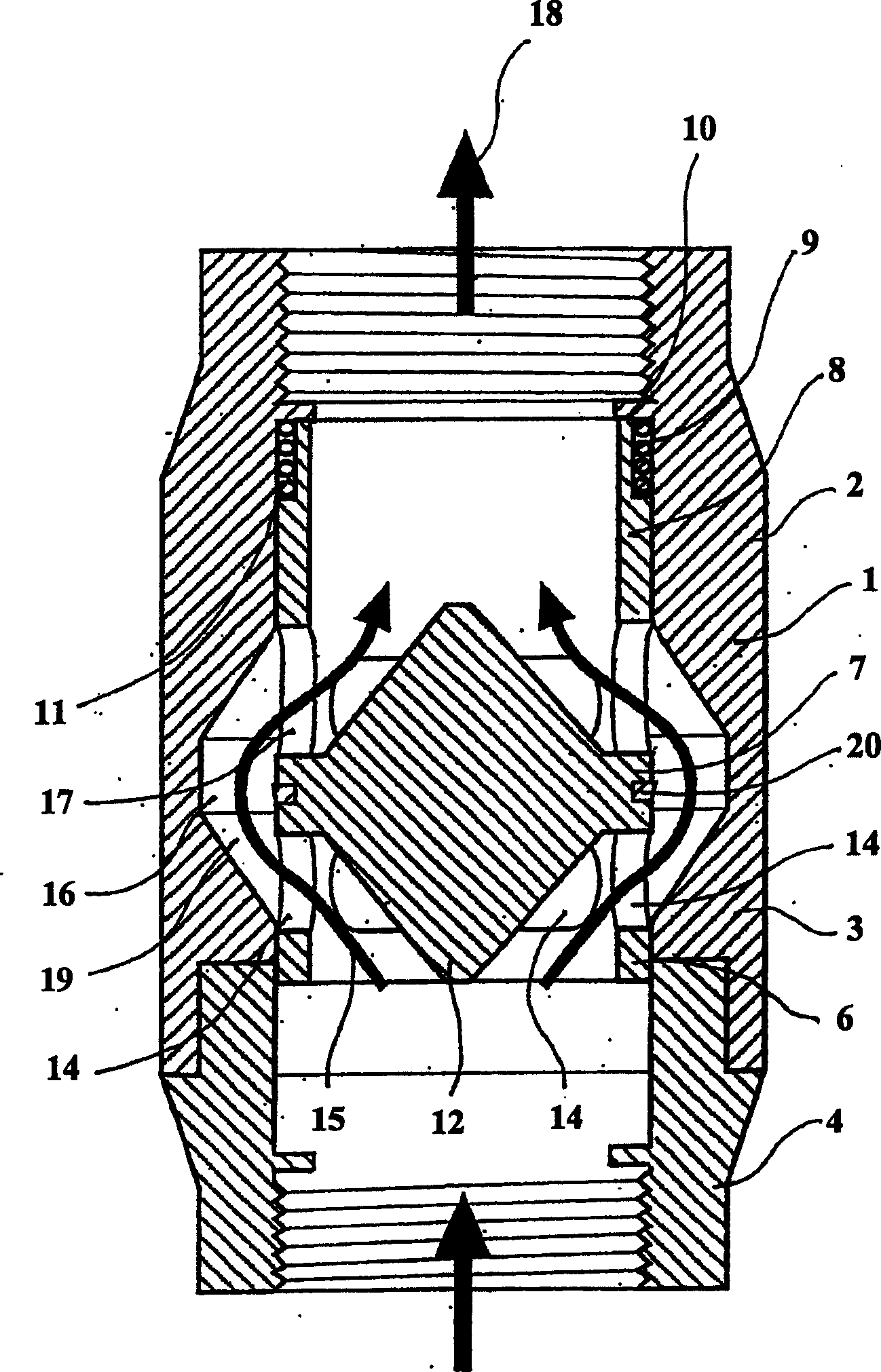
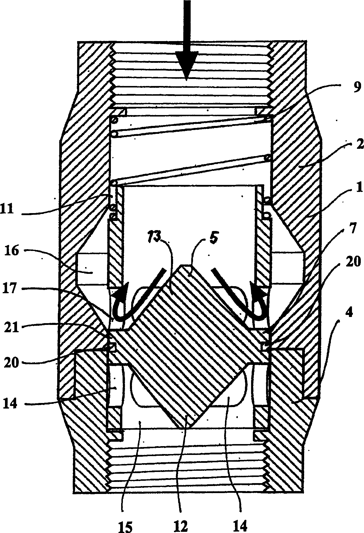
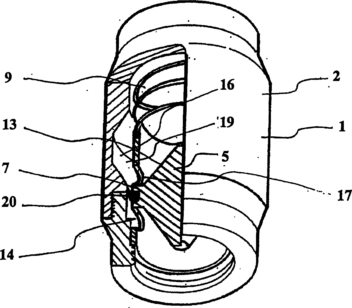
[0048] now refer to Figure 1 to Figure 5 The first embodiment shown, the figure shows a check valve 1, which comprises a main body 2, the main body 2 mainly has an inner hole with a circular cross-sectional shape and consists of two parts, one part is the main body part 3, and the other part is made of threaded Partially connected to this body part is an end portion 4 which enables a reciprocating slide 5 to enter into the body.

[0049] The complex slide 5 in the body 2 has a downstream part 6 , an intermediate part 7 and an upstream part 8 .

[0050] Each of these parts is adapted to slide freely in a respective bore of the body 2 .

[0051] In other words, the reciprocating slider 5 can be figure 1 open position shown and figure 2 It is free to move between the closed positions shown, but is biased by the coil spring 9 held between the stop 10 and the downstream portion 8 of the reciprocating slide 5 .

[0052] As in the figure, especially in the figure 1 As seen in ...


PUM


Abstract

A check valve comprising an outer body having an inner bore, and a reciprocating slide disposed within the inner bore for a closed position relative to the inner bore to prevent liquid flow through the valve and to allow liquid flow through the valve. Elastic means for moving between open positions of the valve and biasing the position of the reciprocating slide towards the closed position, characterized in that the reciprocating slide has a downstream portion, an upstream portion and an intermediate portion, each portion sliding fit in engagement with the bore and such that, when in the closed position, the intermediate portion sealingly engages the bore, and when in the open position, is configured to allow fluid to flow through a passage around the intermediate portion comprising at least The path through this external body.

Description

technical field [0001] Historically, check valves have typically had a valve or poppet within the valve body through which fluid flows, thereby closing the valve. Background technique [0002] The shape and location of such valves or poppets previously used heretofore meant that there was a potential for significant turbulence in the vicinity of the device when it was in the open position, and any such turbulence would cause potential vibration and rotation-related sports. [0003] Techniques tried to date include adding a rod to the valve body valve or poppet located and held within a housing having a central hole through which the rod of the valve or poppet is retained. [0004] Attempts have been made to resist rotational motion with a rod having a non-circular cross-sectional shape that mates with a similarly shaped hole through the center of the frame. [0005] Unfortunately, during this time, such engagement can easily lead to serious failures. [0006] This problem...

Claims


Application Information

Patent Timeline
Patent Type & Authority Applications(China)
IPC IPC(8): F16K3/26F16K15/02
CPCF16K3/265F16K15/026Y10T137/7925Y10T137/3421
Inventor 弗雷德里克·科贝斯
Owner HYDRO FLO HLDG
Why Eureka
Try Eureka