Fuel cell and fuel cell stack

A fuel cell stack and fuel cell technology, applied in the direction of fuel cell groups, fuel cells, fuel cell additives, etc., can solve the problem that multiple cells cannot be positioned on the surface of the separator, so as to improve energy utilization rate and temperature distribution Small, uniform temperature distribution effect

Inactive Publication Date: 2005-09-07
HONDA MOTOR CO LTD
View PDF3 Cites 4 Cited by
  • Summary
  • Abstract
  • Description
  • Claims
  • Application Information

AI Technical Summary

Problems solved by technology

[0016] However, prior art 3 aims to prevent deflection of the battery and separator plates in the horizontal direction
Therefore, prior art 3 does not enable accurate positioning of multiple cells on the surface of the separator

Method used


Image

  • Fuel cell and fuel cell stack
  • Fuel cell and fuel cell stack
  • Fuel cell and fuel cell stack

Examples


Embodiment Construction

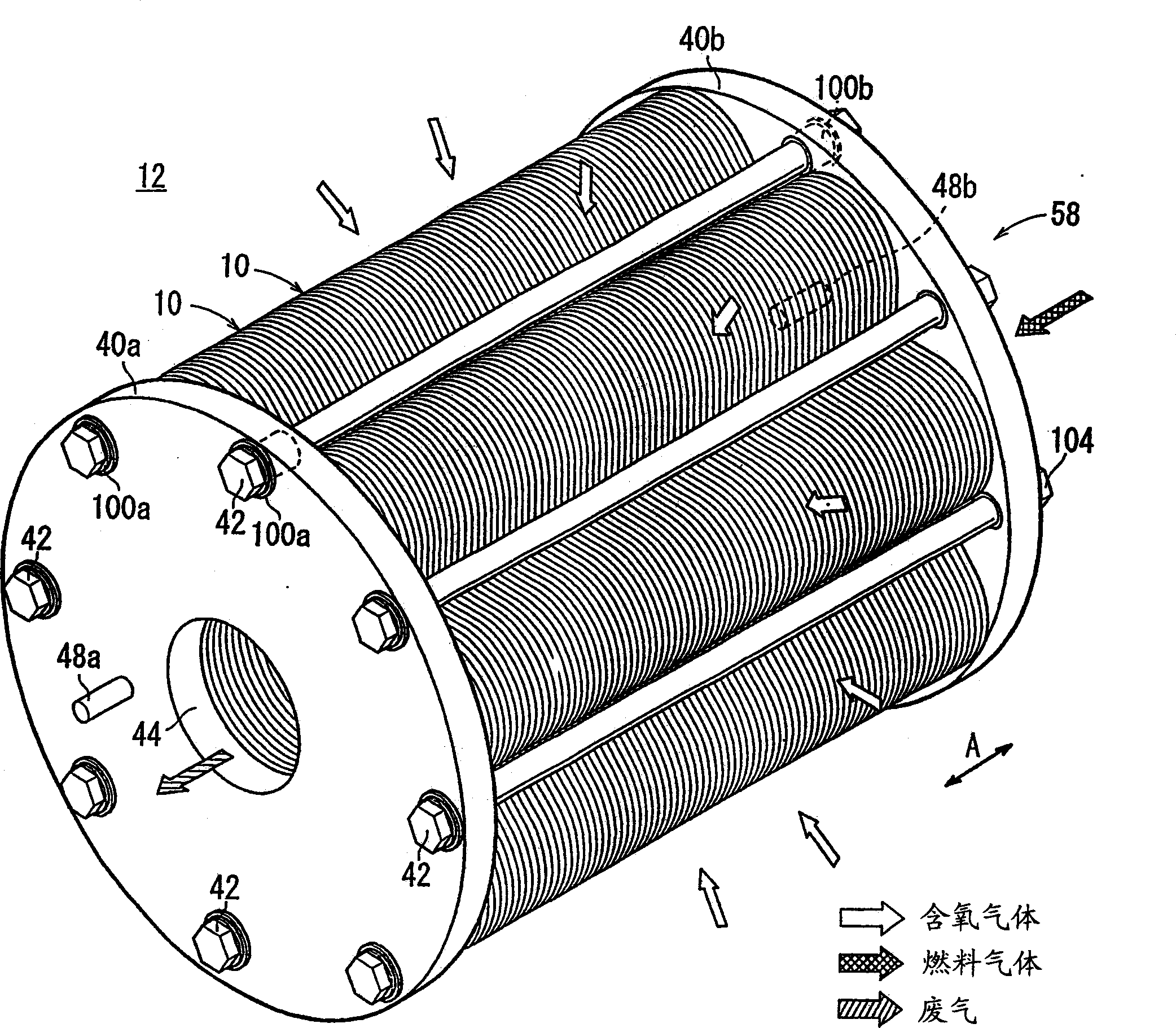
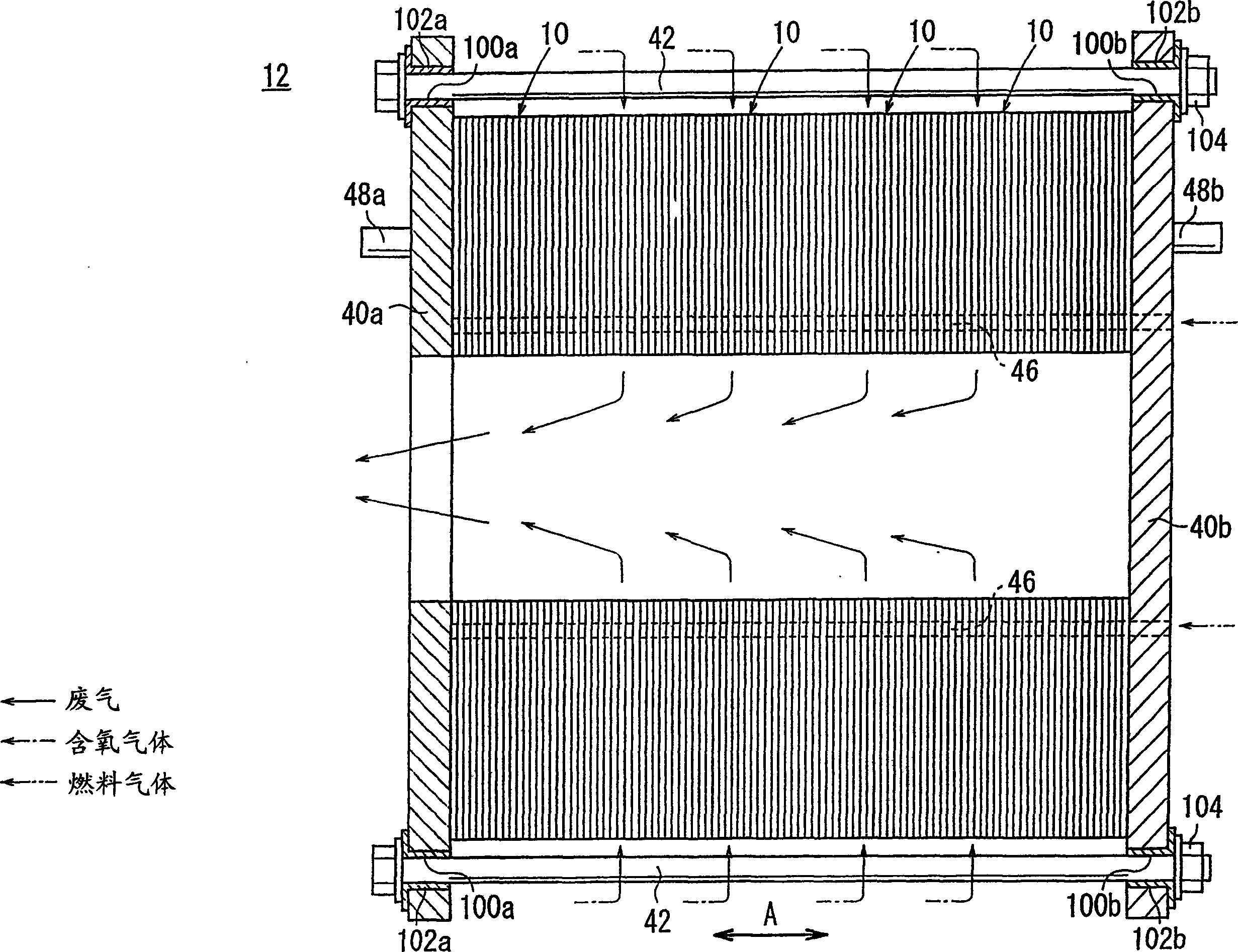
[0066] figure 1 is a perspective view schematically showing a fuel cell stack 12 formed by stacking a plurality of fuel cells 10 according to the first embodiment of the present invention, and figure 2 It is a sectional view showing a part of the fuel cell stack 12 .

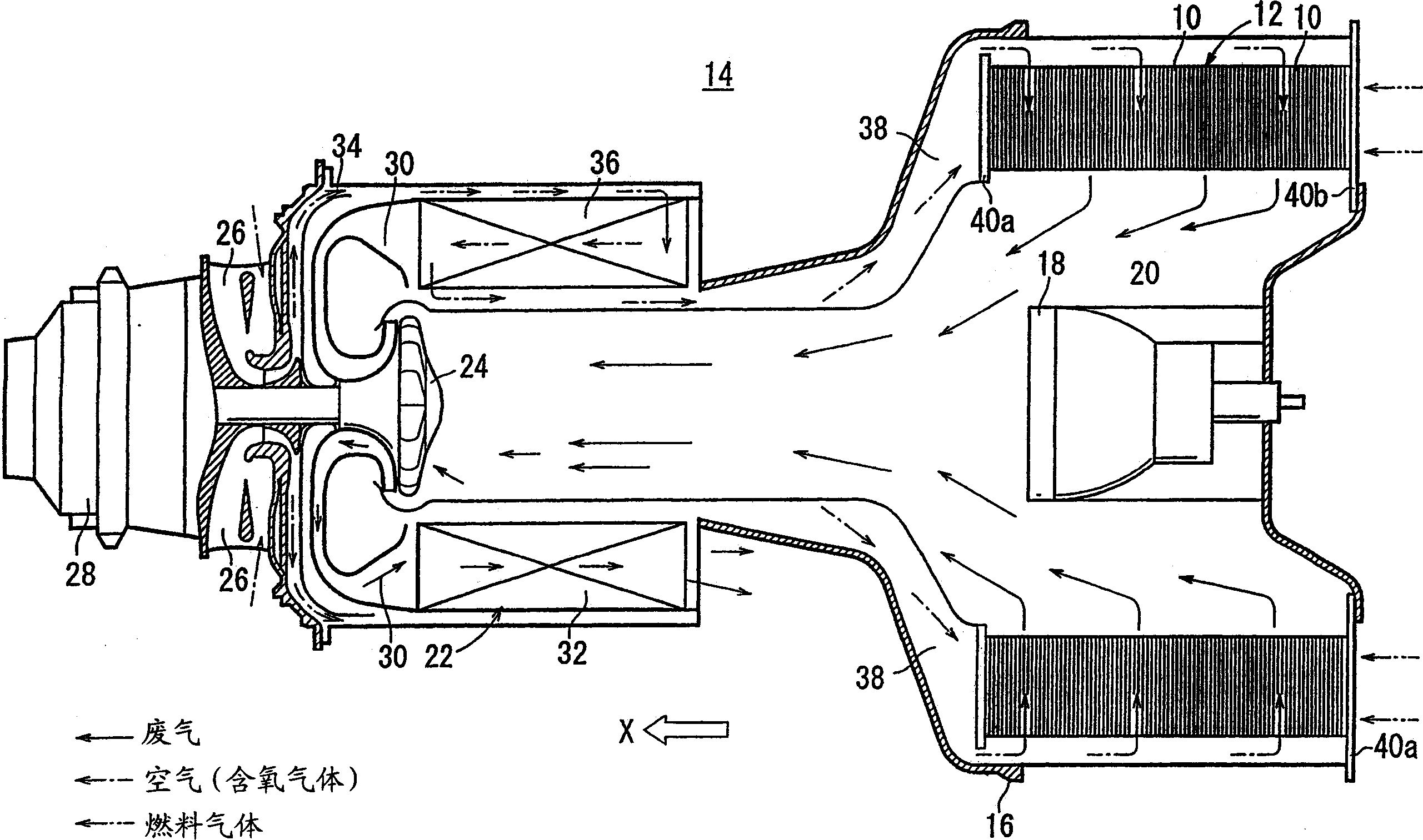
[0067] Fuel cell 10 is a solid oxide fuel cell (SOFC) for stationary and mobile equipment. For example, the fuel cell 10 is mounted on a vehicle. shown in image 3 In the example of the first embodiment, the fuel cell stack 12 is used in a gas turbine 14 . exist image 3 , the shape of the fuel cell stack 12 is the same as figure 1 with figure 2 different, but basically the same structure. The fuel cell stack 12 is disposed in a housing 16 of a gas turbine 14 . The burner 18 is provided at the center of the fuel cell stack 12 . The fuel cell stack 12 discharges exhaust gas, which is a reacted mixture of fuel gas and oxygen-containing gas, into the chamber 20 toward the combustor 18 . The chamber 20...


PUM


Abstract

A fuel cell includes a pair of separators and a plurality of electrolyte electrode assemblies between the separators. The electrolyte electrode assemblies has a small circular disk shape. Eight electrolyte electrode assemblies are arranged along an inner circle and eight electrolyte electrode assemblies are arranged along an outer circle concentric with a circular hole. Each of the separators includes a plurality of plates stacked together. A fuel gas channel for supplying a fuel gas to anodes of the electrolyte electrode assemblies, an oxygen-containing gas channel for supplying an oxygen-containing gas to cathodes of the electrolyte electrode assemblies are formed between the plates.

Description

technical field [0001] The present invention relates to a fuel cell having a disc-shaped electrolyte electrode assembly interposed between separators. Each electrolyte electrode assembly includes an anode, a cathode, and an electrolyte positioned between the anode and the cathode. In addition, the invention also relates to a fuel cell stack formed by stacking a plurality of such fuel cells. Background technique [0002] Typically, solid oxide fuel cells (SOFCs) use ionically conductive solid oxide (eg, stabilized zirconia) electrolytes. The electrolyte is interposed between the anode and the cathode, thereby forming an electrolyte electrode assembly. The electrolyte electrode assembly is interposed between separators (bipolar plates), and the electrolyte electrode assembly and the separator constitute a fuel cell unit for generating electric power. Stacking a predetermined number of fuel cells together forms a fuel cell stack. [0003] In this fuel cell, oxygen-containin...

Claims


Application Information

Patent Timeline
Patent Type & Authority Applications(China)
IPC IPC(8): H01M8/02H01M8/04H01M8/12H01M8/24
CPCH01M8/04089H01M8/0271H01M8/2465H01M8/0247Y02E60/50H01M8/2425H01M8/2483H01M8/2432H01M8/0258H01M8/02H01M8/12
Inventor 角田正
Owner HONDA MOTOR CO LTD
Why Eureka
Try Eureka