Carbon nano tube field emission panel display with focusing electrode structure and fabrication process thereof

A flat panel display and focusing electrode technology, which is applied in the manufacture of electrode systems, the manufacture of discharge tubes/lamps, electrode devices and related components, etc. Improve the service life and luminous efficiency, overcome the short service life, and improve the effect of display brightness

Inactive Publication Date: 2005-06-01
ZHONGYUAN ENGINEERING COLLEGE
View PDF0 Cites 5 Cited by
  • Summary
  • Abstract
  • Description
  • Claims
  • Application Information

AI Technical Summary

Problems solved by technology

[0003] In addition, in order to further improve the service life of the display device, it is necessary to further increase the distance between the anode panel and the control grid while using the high-voltage phosphor as the light-emitting layer, so as to overcome the fatal shortcoming of the short service life of the low-voltage phosphor
However, taking this measure conflicts with controlling electron beam divergence. On the one hand, it is necessa

Method used


Image

  • Carbon nano tube field emission panel display with focusing electrode structure and fabrication process thereof
  • Carbon nano tube field emission panel display with focusing electrode structure and fabrication process thereof
  • Carbon nano tube field emission panel display with focusing electrode structure and fabrication process thereof

Examples


Embodiment Construction

[0029] The present invention will be further described below in conjunction with accompanying drawing and embodiment, but the present invention is not limited to these

[0030] Example.

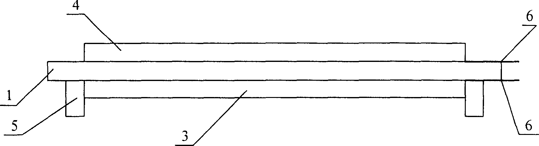
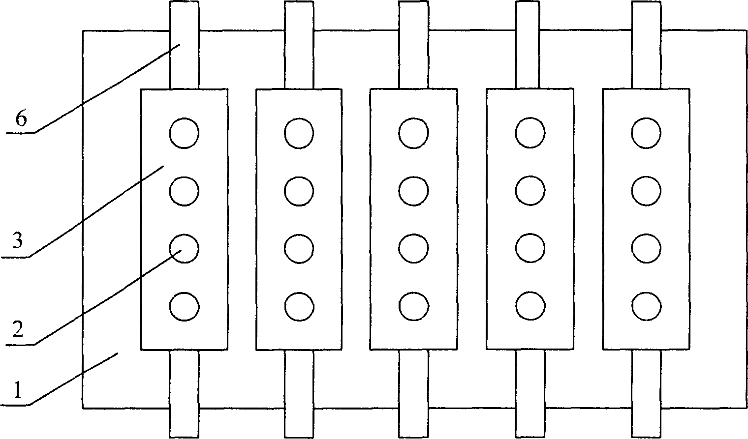
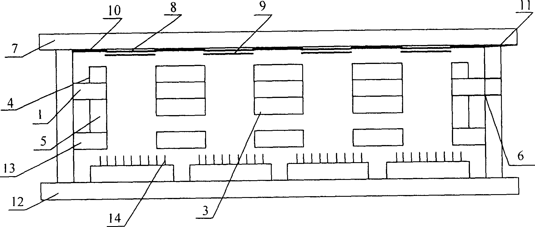
[0031] like figure 1 , 2 , 3, the present invention comprises a sealed vacuum chamber made of a cathode plate 12, an anode plate and a glass enclosure, a carbon nanotube cathode 14 printed on the cathode plate, a fluorescent powder light-emitting layer 9 prepared on the anode panel, located The upper part of the carbon nanotube cathode 14 and the control grid 13 for controlling its electron emission and the focusing electrode structure located between the control grid and the anode plate for focusing the electron beam, and a focusing electrode structure is added between the anode plate and the control grid. The grid structure is used to focus the electrons passing through the control grid to form stable and bright pixels on the anode plate. The focusing electrode structure includes a base ...


PUM


Abstract

The present invention relates to the manufacture of field emission display with carbon nanotube cathode, and is especially field emission plate display with focusing electrode structure and its manufacture. The field emission plate display includes sealed vacuum cavity comprising cathode plate, anode plate and glass frame, carbon nanotube cathode printed on the cathode plate, light emitting phosphor layer on the anode plate, control grid located in the upper part of the carbon nanotube cathode to control its electron emission, and focusing electrode structure located between the control grid and the anode plate to focus electron beam. The present invention can form stable and bright pixels on the anode plate, and has the advantages of simple structure, simple manufacture process, low cost, etc.

Description

technical field [0001] The invention belongs to the intercrossing fields of vacuum science and technology, microelectronic science and technology and nano science and technology, relates to the device production of flat panel display, specifically relates to the content of the device production of a field emission display of a carbon nanotube cathode, in particular to A field emission flat panel display with focusing electrode structure and its manufacturing process. Background technique [0002] Currently, for field emission flat panel displays using carbon nanotubes as cathodes, there is usually no focusing electrode. However, since the electrons emitted from the carbon nanotube cathode have a certain emission angle, they are not all emitted in the direction perpendicular to the anode panel, but spread across the range of angles defined by the control grid holes, so it is easy to A large pixel spot range is formed on the anode panel. At the same time, since there is a ce...

Claims


Application Information

Patent Timeline
IPC IPC(8): H01J9/02H01J29/02H01J29/46H01J31/12
Inventor 李玉魁高宝宁曾凡光刘兴辉
Owner ZHONGYUAN ENGINEERING COLLEGE
Why Eureka
Try Eureka