Vacuum net water suction method and special water drainage board

A drainage board and vacuum technology, applied in construction, infrastructure engineering and other directions, can solve the problems of long construction time, small effective stress, short transmission distance, etc., and achieve the effect of reducing production cost, convenient and reliable construction, and improving construction efficiency.

Inactive Publication Date: 2005-06-08
任再永 +1
View PDF1 Cites 10 Cited by
  • Summary
  • Abstract
  • Description
  • Claims
  • Application Information

AI Technical Summary

Problems solved by technology

Due to the large area covered by the vacuum film, it is difficult to lay it, and because the vacuum is drawn in the entire area, the loss of vacuum is quite large, and the efficiency is very low
Another disadvantage is that the transmission speed of vacuum in soft soil is slow and the transmission distance is short, so the construction time is still long, and the construction process is complicated and the cost is high.
[0006] In order to solve the above problems, Chinese patent 98105035.2 discloses "a method of vacuum dewatering combined with preloading and preloading to strengthen soft soil foundation". The vertical drainage body is connected. Although this method solves the problem of difficult construction of the sealing film and loss of vacuum degree, it greatly increases the difficulty of sealing the sealing end connected to the vertical drainage body. Another disadvantage is that due to the vacuum surface At the top of the vertical drainage body, the effective stress is small, and the construction efficiency is not high

Method used


Image

  • Vacuum net water suction method and special water drainage board
  • Vacuum net water suction method and special water drainage board
  • Vacuum net water suction method and special water drainage board

Examples


Embodiment Construction

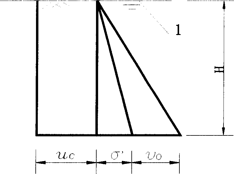
[0052] refer to Figure 5 , 6 , 7, the special drainage plate of the present invention comprises a core plate 6 and a filter membrane layer 2, the two sides of the core plate 6 are provided with vertical drainage passages 7, and a vertical to the vacuum drain 1.

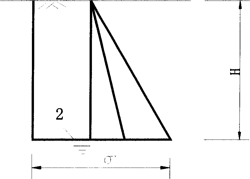
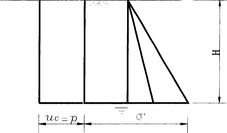
[0053] refer to Figure 8 After cutting off a section of the bottom of the core plate 6 of the drainage board, the bottom of the filter membrane layer 2 is turned up and wrapped around the bottom of the core plate 6, and a certain gap is left at the bottom of the two to facilitate guide water. Drive the above-mentioned treated special drainage board into the soft ground, then cut off a section of the top of the core board 6 of the drainage board, so that the top of the vertical vacuum drainage pipe 1 is exposed, and connected with the horizontal vacuum pipe network 9 directly connected. Clay seal layer 4 is filled in the construction area, and a layer of sealing film 14 is covered on the top of the seal layer. ...


PUM


Abstract

This invention discloses a water-absorbing method by vacuum drainage pipes, the following steps are immersing at least one vertical vacuum drain pipe in the vertical drainage body driving in the vertical diainage pipe into the soft ground; connecting the top of the vacuum drainagepe with the horizontal vacuum pipe network; vacuumize any one or more nodal points. This invention absorbs water by the aid of vertical vacuum drainage pipe imbedded in the drainage body, and the vacuum surface affects directly the bottom of the drainage body and speed the concretion rate because of the agreement between the direction of water flow and gravity. The other advantage is that the joint between pipes can be sealed closely and improves the efficiency of construction.

Description

technical field [0001] The invention relates to a treatment method of soft clay foundation, in particular to a vacuum network point water absorption method and a special drainage board thereof. Background technique [0002] Drainage consolidation method is one of the effective methods to deal with soft clay foundation, which is widely used in transportation, water conservancy, port, construction and other fields; Drainage body, and then use the weight of the building itself, or pre-load preload on the site, so that the pore water in the soil is discharged, gradually consolidated, the foundation subsides, and the strength is gradually increased. [0003] The drainage consolidation method is composed of two parts, the drainage system and the pressurization system. [0004] Drainage system: The main purpose of setting up the drainage system is to change the original drainage boundary conditions of the foundation, increase the passage of pore water discharge, and shorten the dr...

Claims


Application Information

Patent Timeline
Patent Type & Authority Applications(China)
IPC IPC(8): E02D19/20
Inventor 任再永
Owner 任再永
Why Eureka
Try Eureka