Pumped liquid cooling system using a phase change refrigerant

A cooling system and refrigerant pump technology, applied in refrigeration and liquefaction, refrigerators, cooling/ventilation/heating renovation, etc., can solve problems such as damage to compressors, shorten compressor life, etc., and achieve lower temperature drop and lower additional power. The effect of consumption

Inactive Publication Date: 2005-06-08
THERMAL FORM & FUNCTION
View PDF0 Cites 11 Cited by
  • Summary
  • Abstract
  • Description
  • Claims
  • Application Information

AI Technical Summary

Problems solved by technology

This can cause damage to the compressor and shorten the life of the compressor
This is another disadvantage of vapor compression cooling of elements

Method used


Image

  • Pumped liquid cooling system using a phase change refrigerant
  • Pumped liquid cooling system using a phase change refrigerant
  • Pumped liquid cooling system using a phase change refrigerant

Examples


Embodiment Construction

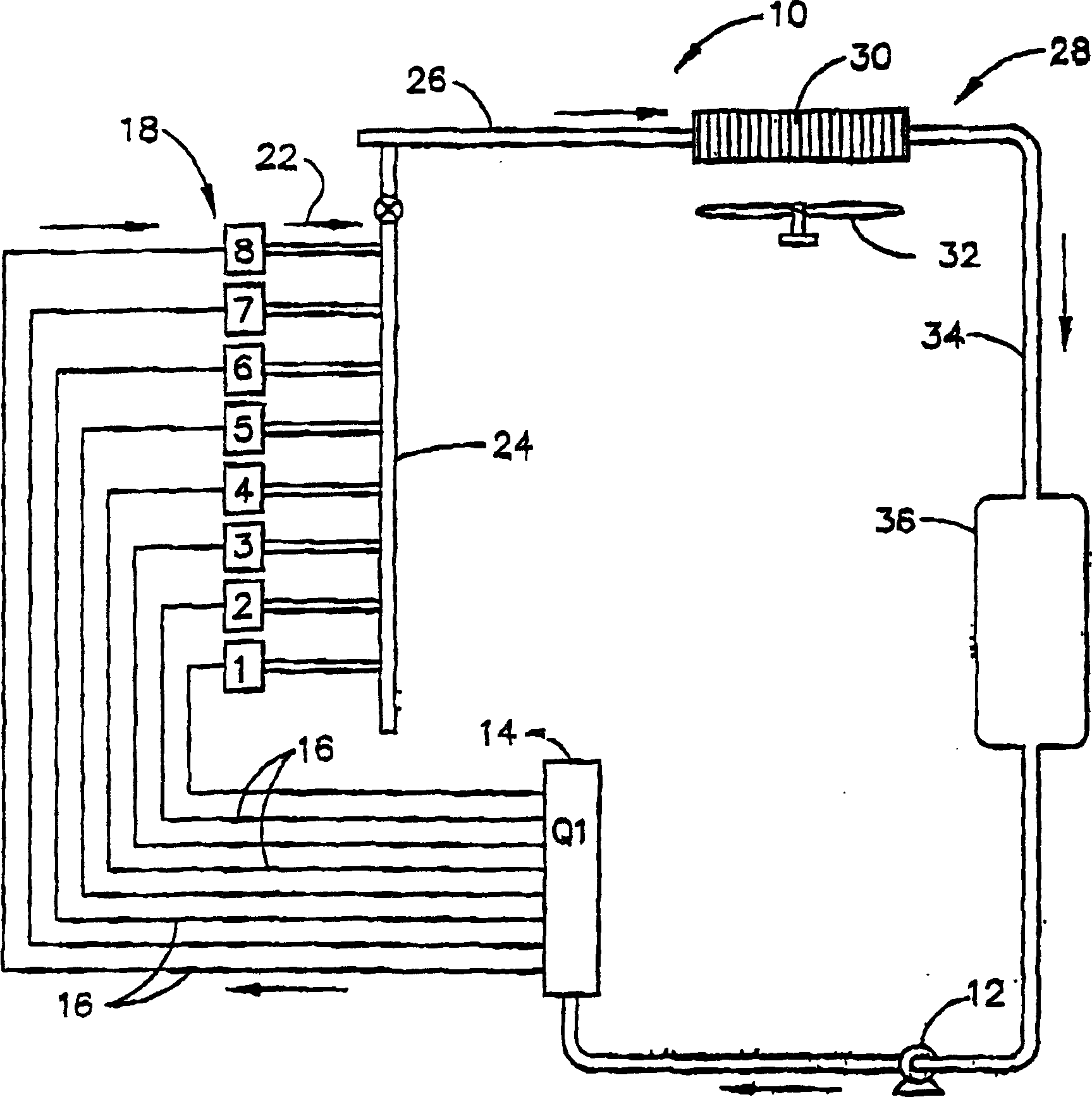
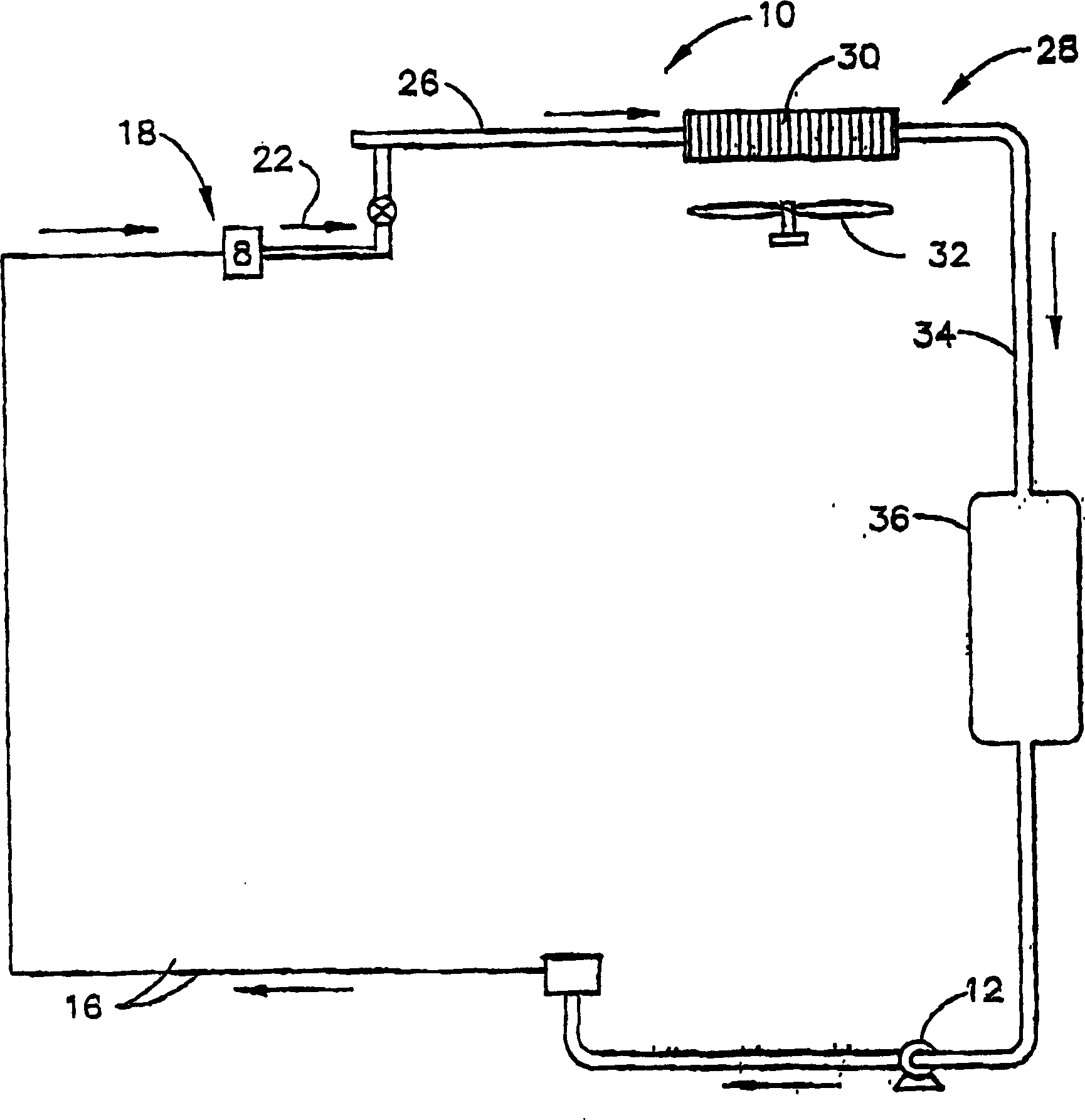
[0017] now refer to Figure 1A and Figure 1B , shows a cooling system 10 that circulates a refrigerant as a working fluid. The refrigerant can be any suitable evaporable refrigerant, such as R-134a. The cooling cycle may start at liquid pump 12 shown as a sealed liquid pump. A pump 12 pumps the liquid refrigerant to a liquid manifold 14 where the liquid refrigerant is distributed to one or more branches or lines 16 . Each branch or line 16 supplies liquid refrigerant from a manifold 14 to a cooling stage 18 . The condensation temperature of the refrigerant is preferably controlled to be higher than the dew point of the surroundings where the cooling stage evaporator unit is located.

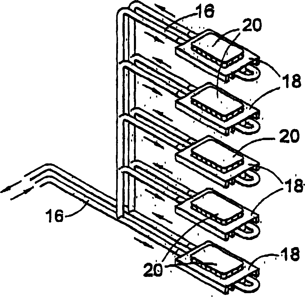
[0018] Such as figure 2 As shown, each cooling stage 18 is in thermal contact with an electrical or electronic component 20 to be cooled such that liquid refrigerant evaporates at system pressure. Depending on how much heat is generated by element 20 , none, some, or all of the liquid refr...


PUM


Abstract

An improved cooling system for cooling the surfaces of electrical and electronic components with low additional power consumption and high heat transfer rates. The components to be cooled are in thermal contact with the cooling table evaporator unit. Refrigerant is circulated to the cooling stage evaporator unit by a liquid refrigerant pump, and the liquid refrigerant is at least partially evaporated by the heat generated by the element. The vapor is condensed through a conventional condenser coil, and the condensed liquid, along with any liquid that has not evaporated, is returned to the pump. The system works approximately isothermally in evaporation and condensation.

Description

[0001] related application [0002] This application is a continuation-in-part of pending application Serial No. 10 / 292,071 filed November 12,2002. technical field [0003] The present invention relates to the cooling of electrical and electronic components, and more particularly to a liquid refrigerant pump which circulates the refrigerant to a plurality of cooling stages / evaporators which are in thermal contact with the electrical or electronic components to be cooled. Background technique [0004] Electrical and electronic components (e.g. microprocessors, IGBT's (Insulated Gate Bipolar Transistor elements), power semiconductor devices, etc.) are usually cooled by air-cooled heat sinks with extended surfaces mounted directly on the surface to be cooled. A fan or blower moves air across the heat sink fins, removing heat generated by the components. With increasing power density, miniaturization of components, and shrinking of packaging, it is sometimes not possible to ade...

Claims


Application Information

Patent Timeline
Patent Type & Authority Applications(China)
IPC IPC(8): F25B23/00G06F1/20H01L23/34H01L23/427H01L23/473H05K7/20
CPCF25B23/006F28D15/0266H01L23/427H01L23/473H01L2924/0002H01L2924/00
Inventor 约瑟夫·马尔萨拉
Owner THERMAL FORM & FUNCTION
Why Eureka
Try Eureka