Method of honing bores

一种珩磨、珩磨条的技术,应用在珩磨工具、珩磨机床、金属加工设备等方向,能够解决高成本等问题

Inactive Publication Date: 2005-06-15
GEHRING GMBH & CO KG
View PDF1 Cites 14 Cited by
  • Summary
  • Abstract
  • Description
  • Claims
  • Application Information

AI Technical Summary

Problems solved by technology

But such cylinder liners lead to higher costs, not only in terms of manufacture, but also in terms of installation of the engine block

Method used


Image

  • Method of honing bores
  • Method of honing bores
  • Method of honing bores

Examples


Embodiment Construction

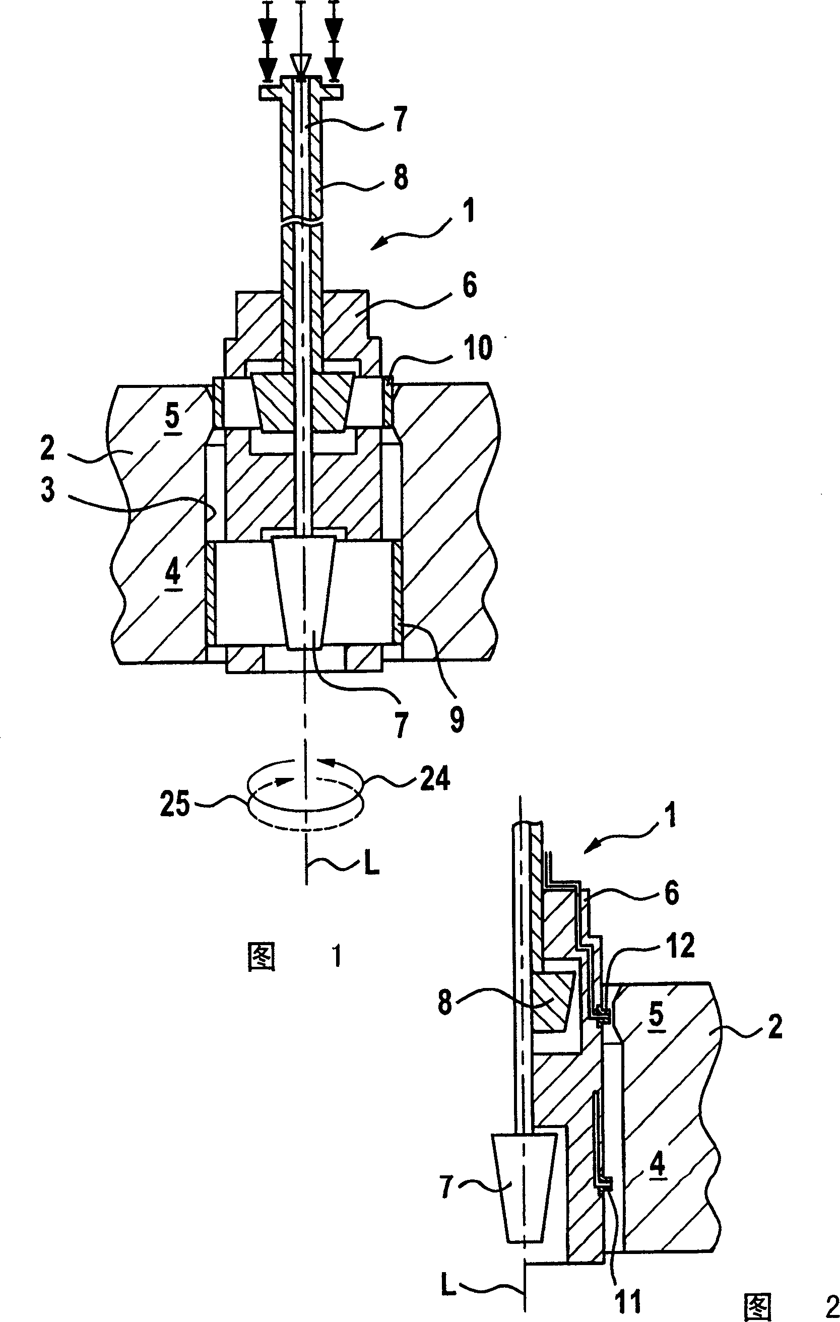
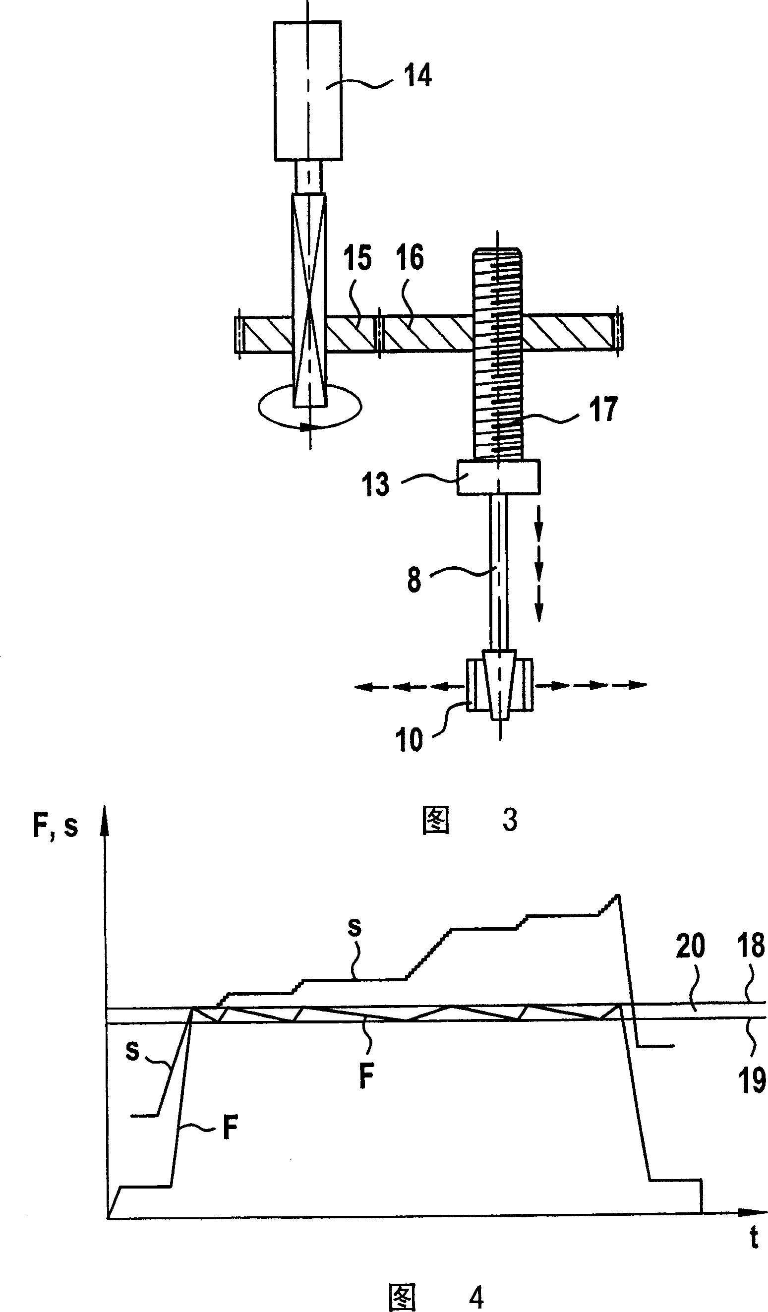
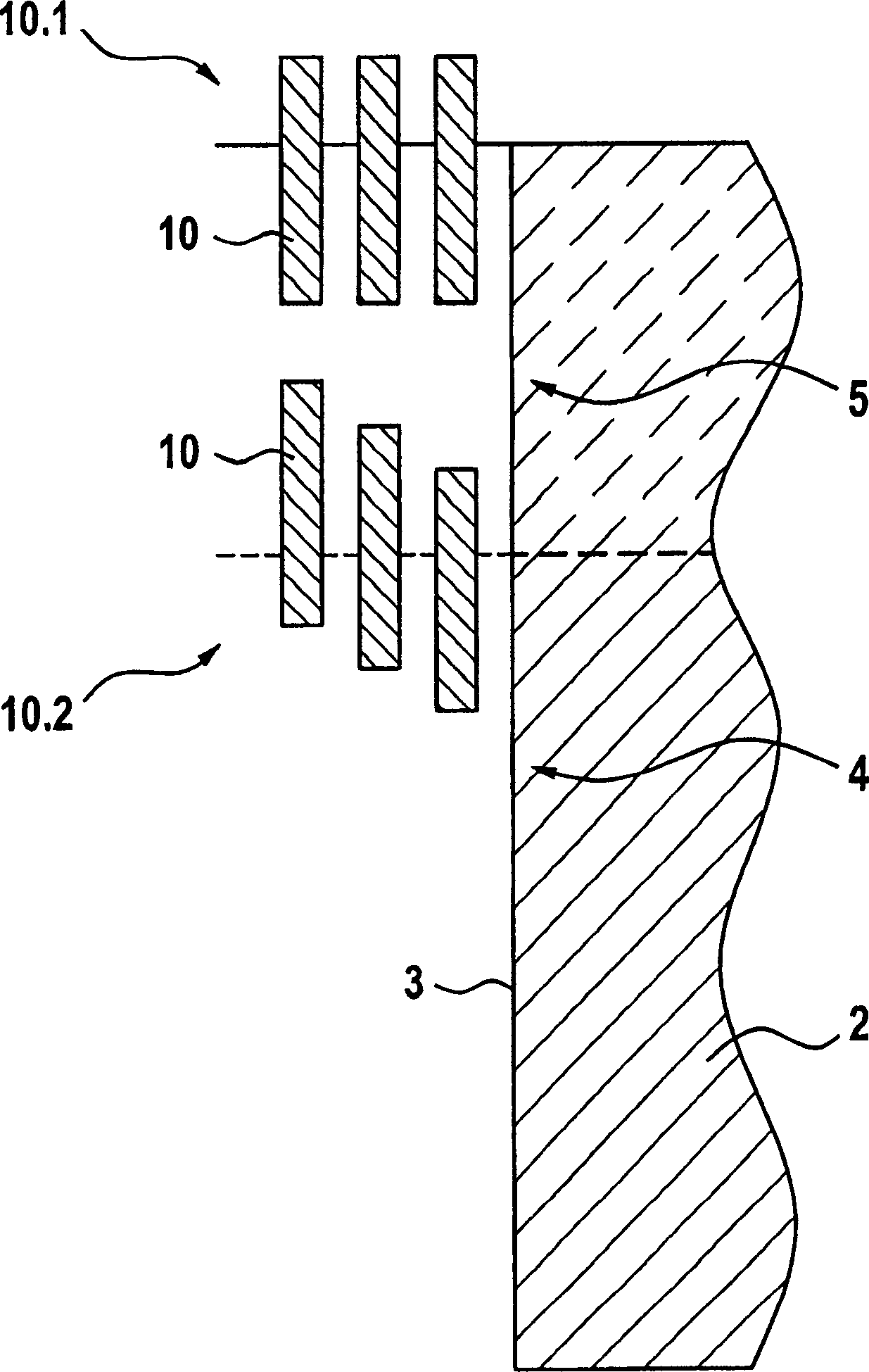
[0018] Figure 1 shows a longitudinal section through a honing tool suitable for coaxial honing. In this case, the honing tool 1 is located in a bore 3 of a workpiece 2, for example the crankcase of an internal combustion engine. The hole 3 comprises an unhardened hole section 4 and a hardened hole section 5 , wherein the hardened hole section 5 is formed at the upper end of the hole 3 in FIG. 1 . The hardened bore section 5 can be produced, for example, by induction hardening. The honing tool 1 comprises a tool head 6 with a radially expandable honing stone 10 and a radially expandable guide strip 9 . The guide bar 9 bears on the wall of the unhardened hole section 4 and applies a predetermined force to the honing stone 10 to press against the wall of the hardened hole section. A first feed device 7 for the guide strip 9 and a second feed device 8 for the honing stone 10 are provided. The second feeding device 8 may be a force-controlled electromechanical stepping feeding d...


PUM


Abstract

The invention describes a method for honing a hole (3) having two hole sections (4, 5) connected one behind the other in the axial direction of the hole (3), the surfaces to be machined of the hole sections having different hardnesses. The honing tool (1) is supported radially in the unhardened bore section (4), while the hardened bore section (5) is machined and thus ground with the honing stick (10) mounted on the honing tool (1). drop material. The feed adjustment of the honing stick (10) takes place in a force-controlled electromechanical feed and the working stroke of the honing tool is continuously varied at least towards the end of the honing process.

Description

technical field [0001] The present invention relates to a method of honing bores and in particular cylinder bores of crankcases of internal combustion engines. Background technique [0002] In truck engines, centrifugally cast cylinder liners are often used as cylinder running surfaces because this material is more wear-resistant than the engine block material. However, such a cylinder liner entails relatively high costs, not only in terms of production, but also in terms of installation of the engine block. Therefore, it has long been proposed to locally harden the running surfaces of the cylinders in the engine block in the upper reversing zone of the piston movement, in order thereby to obtain a higher wear resistance. A separate cylinder liner can thus be dispensed with. As far as hardening is concerned, for example by means of a laser, a more economical or cost-effective alternative is induction hardening. Non-concentric hole shrinkage occurs during induction hardeni...

Claims


Application Information

Patent Timeline
Patent Type & Authority Applications(China)
IPC IPC(8): B24B33/02B24B33/08
CPCB24B33/02B24B33/083
Inventor U·克林克J·维德霍尔德J·沃尔夫
Owner GEHRING GMBH & CO KG
Why Eureka
Try Eureka