Ejecting and compensating mechanism of disk brake having brake for parking

A disc brake and compensation mechanism technology, applied in the direction of brakes, brake components, brake types, etc., can solve the problems of large volume of the brake device, affecting the sealing effect, and difficult manufacturing process

Inactive Publication Date: 2005-06-15
刘连忠
View PDF1 Cites 12 Cited by
  • Summary
  • Abstract
  • Description
  • Claims
  • Application Information

AI Technical Summary

Problems solved by technology

The existing problem is: due to the limitation of its structural characteristics, the mandrel is always in the state of axial movement in the piston during the parking brake, so the mandrel is prone to axial movement, which a...

Method used


Image

  • Ejecting and compensating mechanism of disk brake having brake for parking

Examples


Embodiment Construction

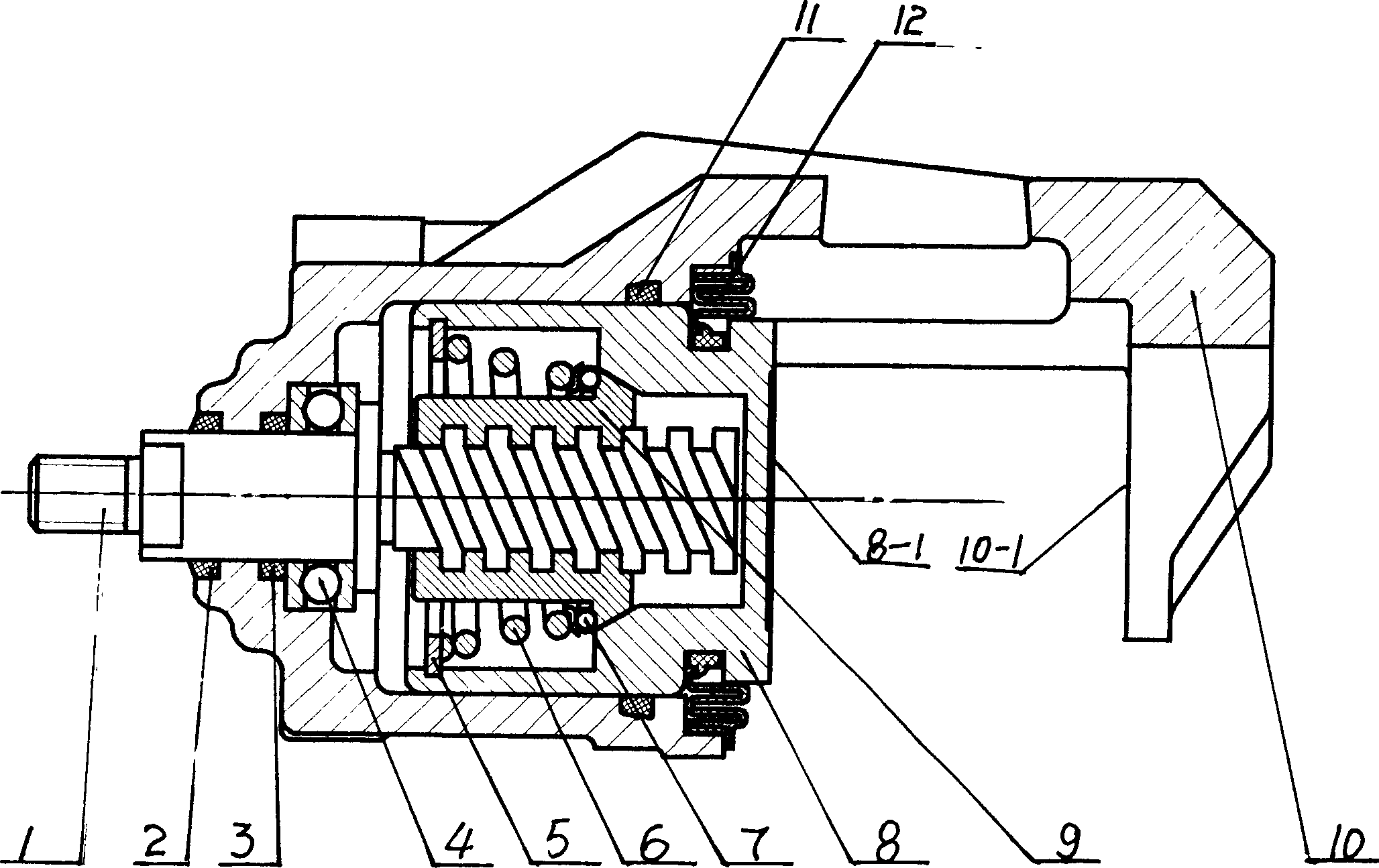
[0007] The specific implementation of the present invention will be further described in conjunction with the accompanying drawings and examples.

[0008] see figure 1 , the present invention includes: rotating shaft 1, dustproof ring 2, rotating shaft seal ring 3, thrust bearing 4, inner circlip 5, truncated cone coil spring 6, thrust bearing 7, piston 8, rectangular nut 9, cylinder body 10, piston seal Ring 11, piston dust-proof ring 12, piston 8 is housed in the cylinder body 10, and the piston 8 has a closed outer end wall 8-1, which together with the brake jaw 10-1 provided on the cylinder body 10 constitutes a clamping friction plate The braking surface of the mechanism is equipped with an automatic ejection and automatic compensation device composed of a screw, a rectangular nut, and an elastic element. It has a rotating shaft 1 that can rotate but cannot move axially. The brake cable is connected and realizes interlocking. One end of the shaft 1 provided with a screw ...


PUM


Abstract

A projection and compensation mechanism for the disk brake with parking brake features that the hydraulic brake and the mechanical brake are combined, and said mechanical brake has an automatic projection and compensation unit consisting of leading screw, rectangular nut and elastic element. Its advantages are simple structure, and high reliability.

Description

Technical field: [0001] The invention belongs to the technical field of vehicle brakes, and relates to a disc brake ejection and compensation mechanism with a parking brake. Background technique: [0002] In the prior art, a 95192863.5 patent is disclosed, the structure of which is composed of ejection and compensation parts, that is, a slope member is set on the brake shaft sleeve, and the spherical support body and the spherical support on the slope member are used. The function of the ring-shaped plate-shaped adjustable slope member corresponding to the supporting body is to withstand the piston spindle and drive the piston to move, so as to realize the automatic compensation function during the parking braking process. The existing problem is: due to the limitations of its structural characteristics, the mandrel is always in the state of axial movement in the piston during parking braking, so the mandrel is prone to axial movement, which affects the sealing effect. More...

Claims


Application Information

Patent Timeline
IPC IPC(8): B60T1/06F16D71/02
Inventor 刘连忠
Owner 刘连忠
Why Eureka
Try Eureka