

Method and apparatus for data reproducing using iterative decoding in a disk drive
An iterative decoding, disk drive technology, applied in the direction of error correction/detection using linear codes, error correction/detection using block codes, recording/reproduction/deletion methods, etc., can solve problems such as performance degradation
- Summary
- Abstract
- Description
- Claims
- Application Information
AI Technical Summary
Problems solved by technology
Method used
Image

Examples
no. 1 example
[0022] A first embodiment of the present invention will be described below with reference to the drawings.
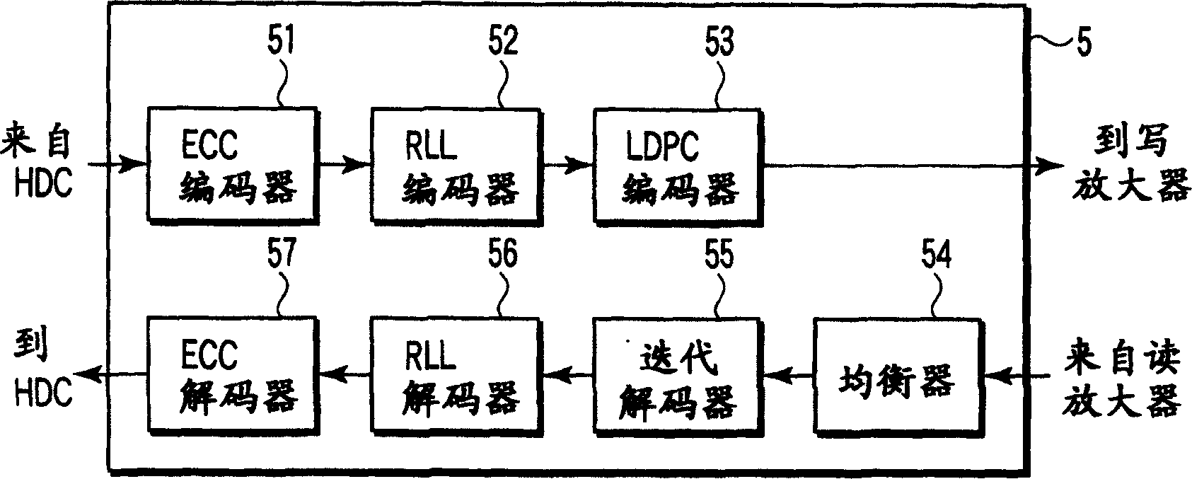
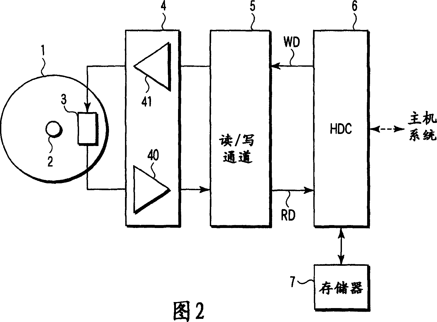
[0023] figure 1 is a block diagram showing the main part of the read / write channel 5 which is the data reproducing device related to the present embodiment. FIG. 2 is a block diagram showing the main part of the disk drive including the read / write channel 5. As shown in FIG.
[0024] (Disk drive structure)
[0025] A disk drive as shown in FIG.
[0026] A spindle motor (SPM) 2 rotates the disk 1 . The magnetic head 3 includes a read head device (GMR device) and a write head device, and reads data from the disk 1 by the read head device. In addition, the magnetic head 3 writes data on the disk 1 by a write head device.
[0027] The pre-amplification circuit 4 has a read amplifier 40 that amplifies a data signal (read data signal) read by the read head device and sends the amplified data signal to the read / write channel 5 . Furthermore, the pre-amplification circuit...
no. 2 example
[0056] Figure 8 with Figure 9 is a block diagram showing the main parts of the R / W channel 5 and the iterative decoder 55 related to the second embodiment.
[0057] That is, if Figure 8 As shown in , the R / W channel 5 of this embodiment is constructed in such a way that the recursive systematic convolutional (RSC) encoder 80 of the outer code is cascaded in series with the PR channel of the inner code. Therefore, if Figure 9 As shown in , the iterative decoder 55 performs an iterative decoding process by the channel decoder 550 for performing the decoding process of the PR pass of the inner code and the RSC decoder 90 for performing the decoding process of the RSC encoding group of the outer code.
[0058] In this respect, the operations in the iterative decoder 55 including the operations of the LLR adjuster 551 and the RLL error detector 552 are the same as in the case of the first embodiment.
no. 3 example
[0060] Figure 10 with Figure 11 is a block diagram showing main parts of the R / W channel 5 and the iterative decoder 55 related to the third embodiment.
[0061] That is, if Figure 10 As shown in , the R / W path 5 of this embodiment is constructed in such a way that the parity-check (PC) encoder 100 of the outer code is cascaded in series with the PR path of the inner code. Therefore, if Figure 11 As shown in , the iterative decoder 55 performs an iterative decoding process by the channel decoder 550 for performing the decoding process of the PR pass of the inner code and the PC decoder 110 for performing the decoding process of the RSC encoding group of the outer code.
[0062] In this respect, the operations in the iterative decoder 55 including the operations of the LLR adjuster 551 and the RLL error detector 552 are the same as in the case of the first embodiment.
PUM
 Abstract
Description
Claims
Application Information