Communication relay apparatus and communication receiver

a relay apparatus and communication receiver technology, applied in the field of digital communication networks, can solve problems such as providing sub-optimal data transmission opportunities

Inactive Publication Date: 2006-12-28
NTT DOCOMO INC
View PDF7 Cites 33 Cited by
  • Summary
  • Abstract
  • Description
  • Claims
  • Application Information

AI Technical Summary

Benefits of technology

[0009] Thus, it is the object of the present invention to provide a

Problems solved by technology

However, the known solutions only provide sub-optimal possibility to transmi

Method used


Image

  • Communication relay apparatus and communication receiver
  • Communication relay apparatus and communication receiver
  • Communication relay apparatus and communication receiver

Examples


Embodiment Construction

[0034] Equal or similar elements are denoted with equal or similar reference signs, wherein a repetition of the explanation of these elements is omitted.

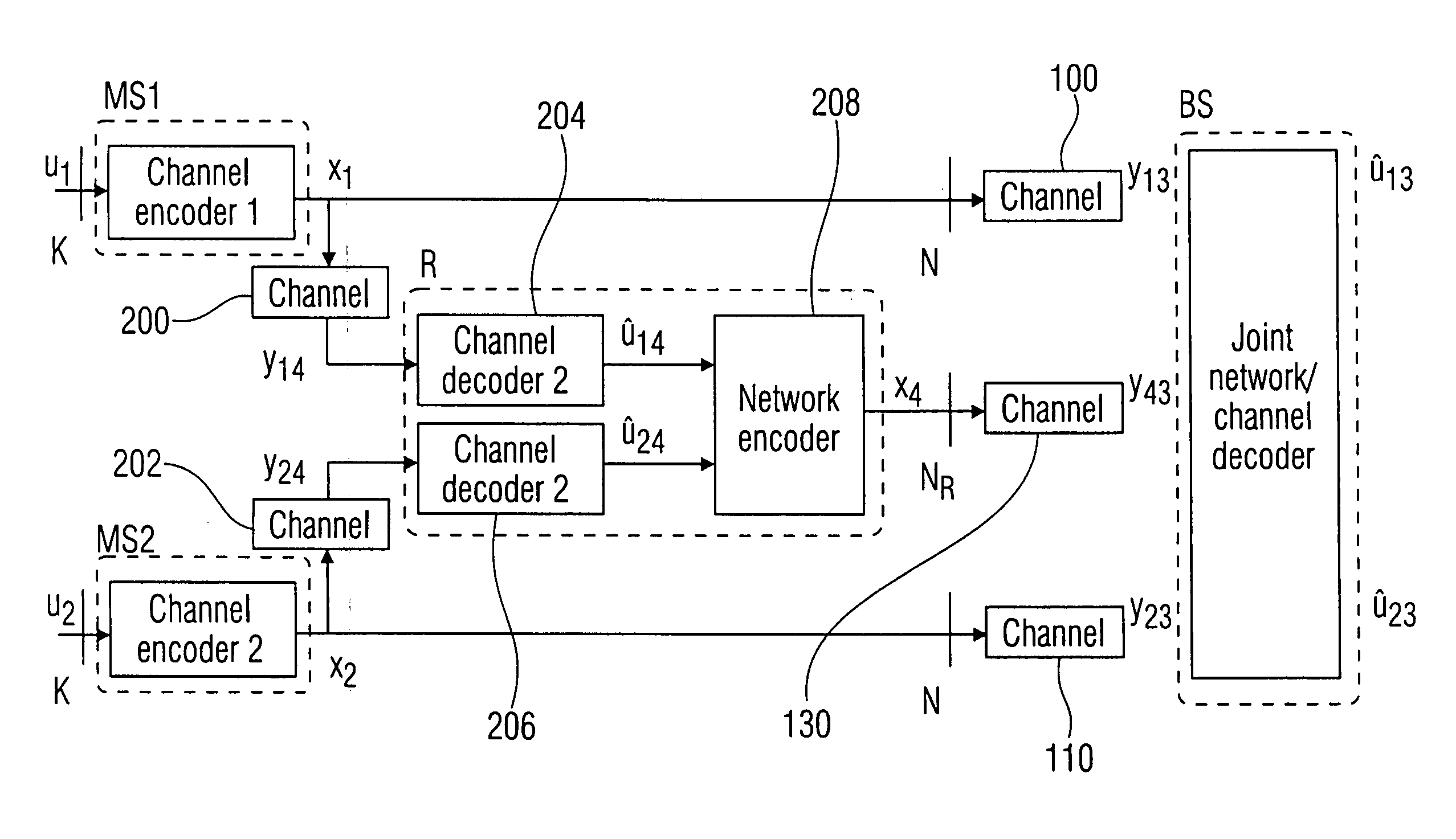
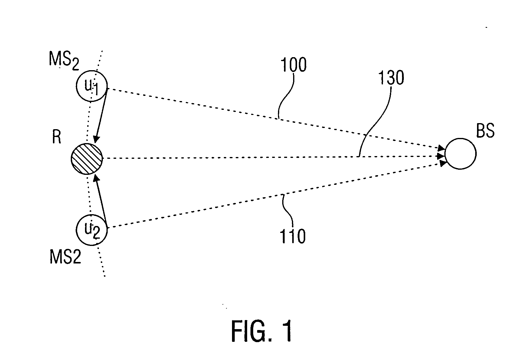
[0035] In a network with two sources, one relay and one sink (e.g. uplink in a cellular based mobile communication system as shown in FIG. 1) the two sources (for example users) MS1 and MS2 want to transmit statistically independent data which are segmented in blocks u1 and u2 with the block length K to the sink (base station) BS. In order to support the transmission, even in the case of a weak first channel 100 or a weak channel 110, a relay R is used which is provided with data from a first source MS1 and a second source MS2. The relay R can then transmit the information received from the first and second sources MS1 and MS2 via the relay channel 130 to the sink BS.

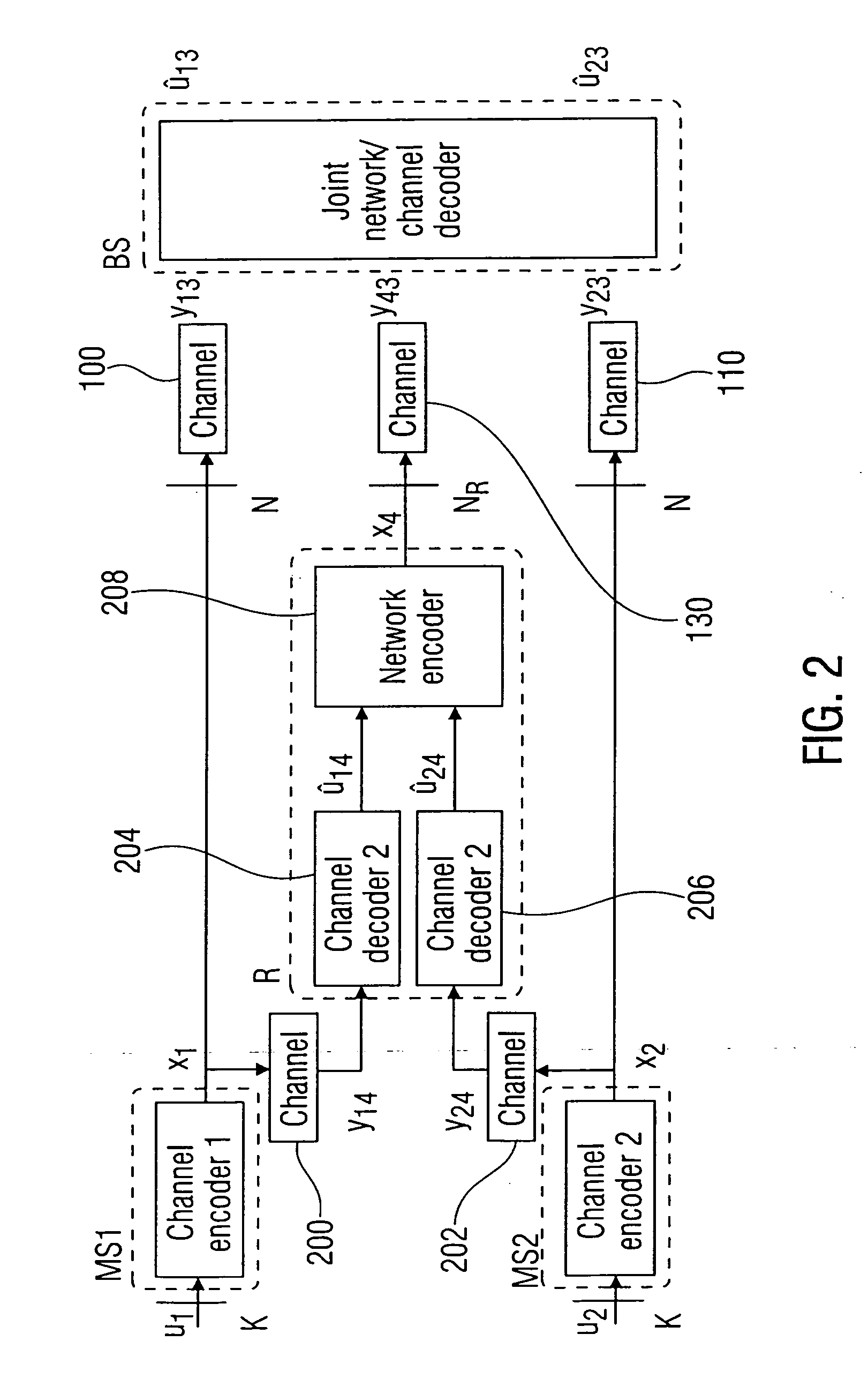
[0036] A block diagram of an embodiment of the inventive approach is depicted in FIG. 2. The information units (e.g. bits) u1 and u2 are protected against transmissio...


PUM


Abstract

A communication relay apparatus for providing a network-encoded information unit sequence comprises a first channel decoder which is configured to supervise a first wireless channel, to receive a first channel-encoded sequence of information units from a first data source via the first wireless channel and to decode the first channel-encoded sequence of information units to obtain a first decoded sequence of information units. Furthermore, the communication relay apparatus comprises a second channel decoder which is configured to supervise a second wireless channel, to receive a second channel-encoded sequence of information units from a second data source via the second wireless channel and to decode the second channel-encoded sequence of information units to obtain a second decoded sequence of information units, the first and second wireless channels being different from each other. Finally, the communication relay apparatus comprises a network-encoder which is configured to encode information of the first and second decoded sequences of information units into the network-encoded information unit sequence and wherein the network-encoder is further configured to wirelessly transmit the network-encoded information unit sequence to a data sink.

Description

BACKGROUND OF THE INVENTION Cross-Reference to Related Application [0001] This application claims priority from European Patent Application No. 05011865.2, which was filed on Jun. 1, 2005, and is incorporated herein by reference in its entirety. Field of the Invention [0002] The present invention relates to digital communication systems, and more particularly to digital communication networks. Description of Related Art [0003] A digital communication network consists of one or several sources, intermediate nodes (relays) and one or several sinks. Information has to be transmitted from the source(s) to the sink(s) over the network whereas the nodes are often connected by band-limited channels with time-varying disturbance. The technical aim is to provide a high quality communication with low bit error rate whereas the total transmission power is restricted. [0004] A known solution to transmit data from a source to a sink over a network is to route the information through the network....

Claims


Application Information

Patent Timeline
IPC IPC(8): H04Q7/28H04J3/04
CPCH03M13/1102H03M13/3761H03M13/6306H04L2001/0097H04L1/0057H04L1/02H04L1/16H04B7/15521Y02D30/70
Inventor HAUSL, CHRISTOPHSCHRECKENBACH, FRANKOIKONOMIDIS, IOANNISBAUCH, GERHARD
Owner NTT DOCOMO INC
Why Eureka
Try Eureka