

Sheet-like object spreader
A sheet and stretching machine technology, which is applied in the direction of winding strips, thin material handling, transportation and packaging, etc., to achieve the effect of simple structure and reduced walking resistance
- Summary
- Abstract
- Description
- Claims
- Application Information
AI Technical Summary
Problems solved by technology
Method used
Image

Examples
no. 1 example
[0035] Borrow below Figure 1-Figure 4 A first embodiment of the present invention will be described.
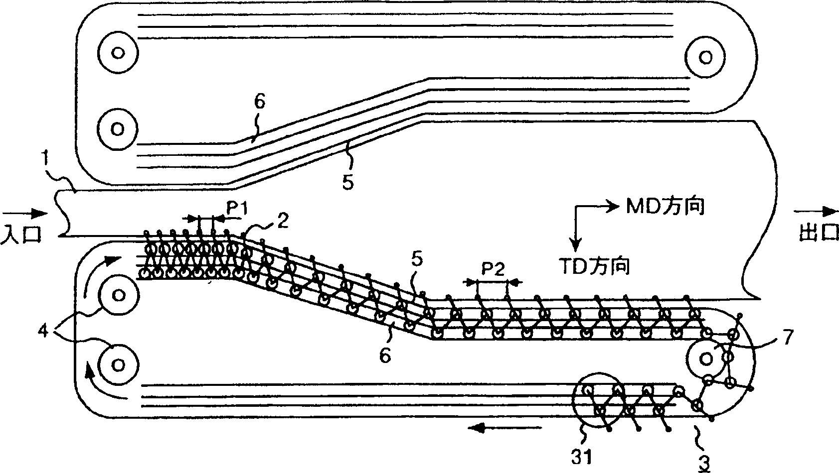
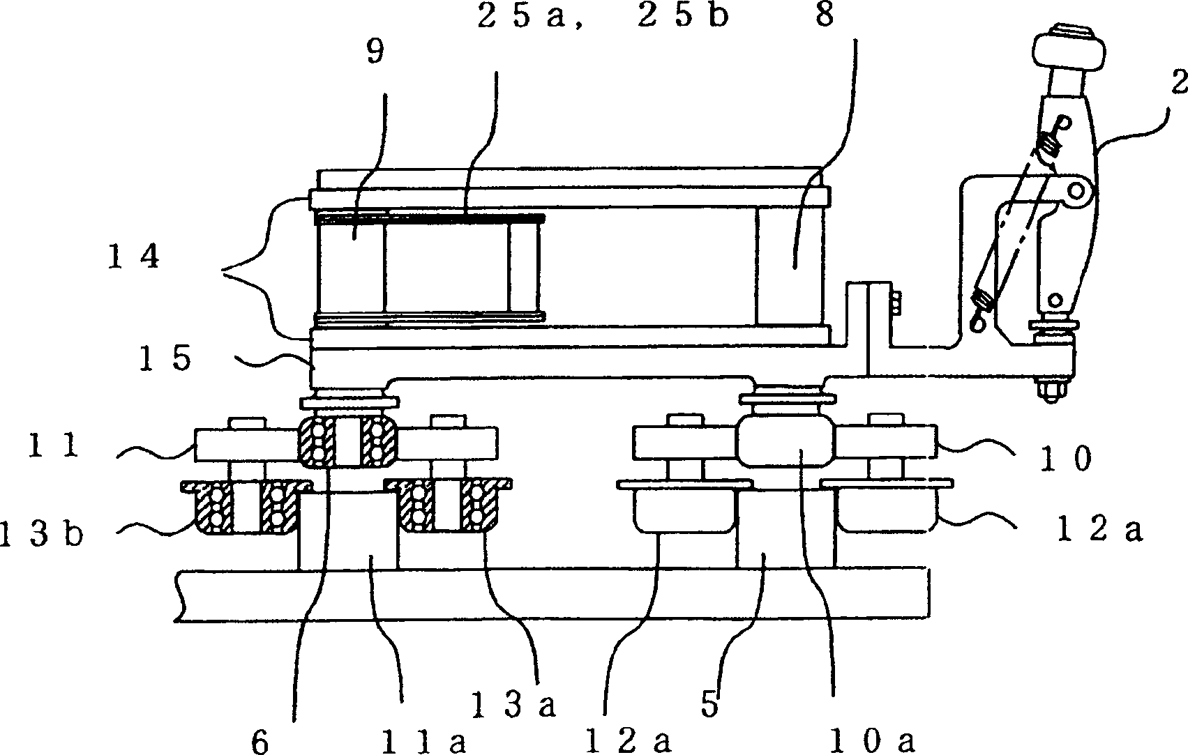
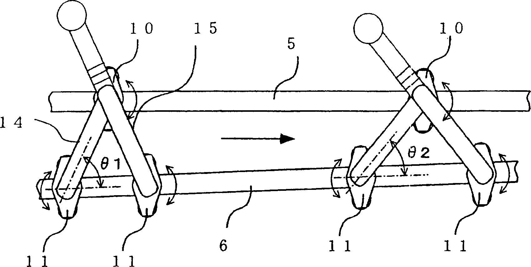
[0036] figure 1 is a plan view of the synchronous biaxial stretching machine as the first embodiment of the present invention, figure 2 It is a cross-sectional view of the equal-length link device 31 as the first embodiment, and its configuration and operation are as follows.
[0037] On both sides of the sheet 1, there is a ring-shaped link device 3 with a plurality of clamping devices 2 that hold the end of the sheet 1 (a part of the link and the ring-shaped link on one side are omitted in the figure) , It is composed of a plurality of equal-length link devices 31 formed into a folding rule shape. In addition, the endless link device 3 is driven by the sheet inlet side sprocket 4 . In addition, an opening and closing device (not shown) such as an opening and closing guide provided at the entrance opens and closes the clamping device 2 and clamps the sheet 1, and is he...
no. 2 example
[0055] Borrow below Figure 7 A second embodiment of the present invention will be described.
[0056] Figure 7 It is a cross-sectional view of an equal-length link device 31 as a second embodiment of the present invention. The difference from the first embodiment is that radial bearings without flanges are used instead of radial bearings 12 and 13 with flanges. 16 (16a, 16b) and 17 (17a, 17b), the ball bearings 18, 19 as rolling bearings are arranged at the lower ends of the connecting rod shafts 8, 9, and the ball bearings 18, 19 roll on the guiding rails 5, 6, The weight of the equal-length linkage is supported by spherical bearings. Furthermore, it is also possible to replace the ball bearings 18, 19 with roller bearings.
[0057] If the second embodiment is adopted, in addition to the effects of the first embodiment, complete rolling friction can be realized, the weight of the link device can be further reduced, and a stretching machine that is advantageous for high s...
no. 3 example
[0059] Borrow below Figure 8 and Figure 9 A third embodiment of the present invention will be described. Figure 8 It is a cross-sectional view of an equal-length connecting rod 31 as a third embodiment of the present invention, which is different from the first embodiment in that the bearing holders 10 and 11 are provided with restraining bearing holders 10 and 11 against the connecting rod. Rotation motion limiting means 216, 217 for the free rotation of the center shafts of the shafts 8, 9. The rotational movement restricting means 216 and 217 are configured to restrict the rotational movement of the bearing holders 10 and 11 by imparting a rotational force in one direction by, for example, a torsion spring or the like.
[0060] By using the equal-length link device constructed in this way, it is possible to prevent vibration during high-speed travel. That is, for smooth running, some gaps are provided in a pair of radial bearings provided across the guide rail. Adjus...
PUM
 Abstract
Description
Claims
Application Information