Motor with reduction mechanism and power seat motor with reduction mechanism
A technology of reduction mechanism and motor box, applied in the direction of movable seats, components with teeth, electromechanical devices, etc., to achieve the effect of reducing size
- Summary
- Abstract
- Description
- Claims
- Application Information
AI Technical Summary
Problems solved by technology
Method used
Image

Examples
Embodiment Construction
[0031] An embodiment of the present invention will now be described with reference to the accompanying drawings.
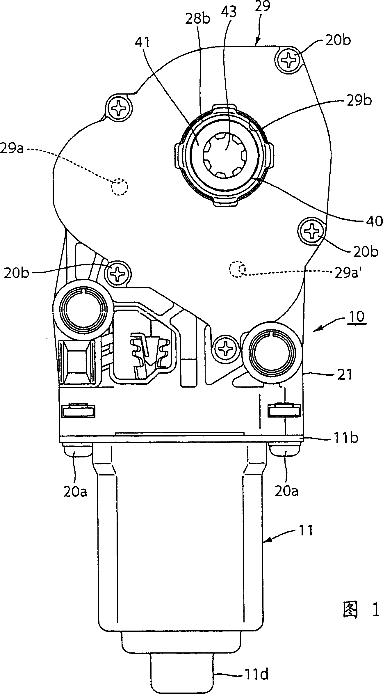
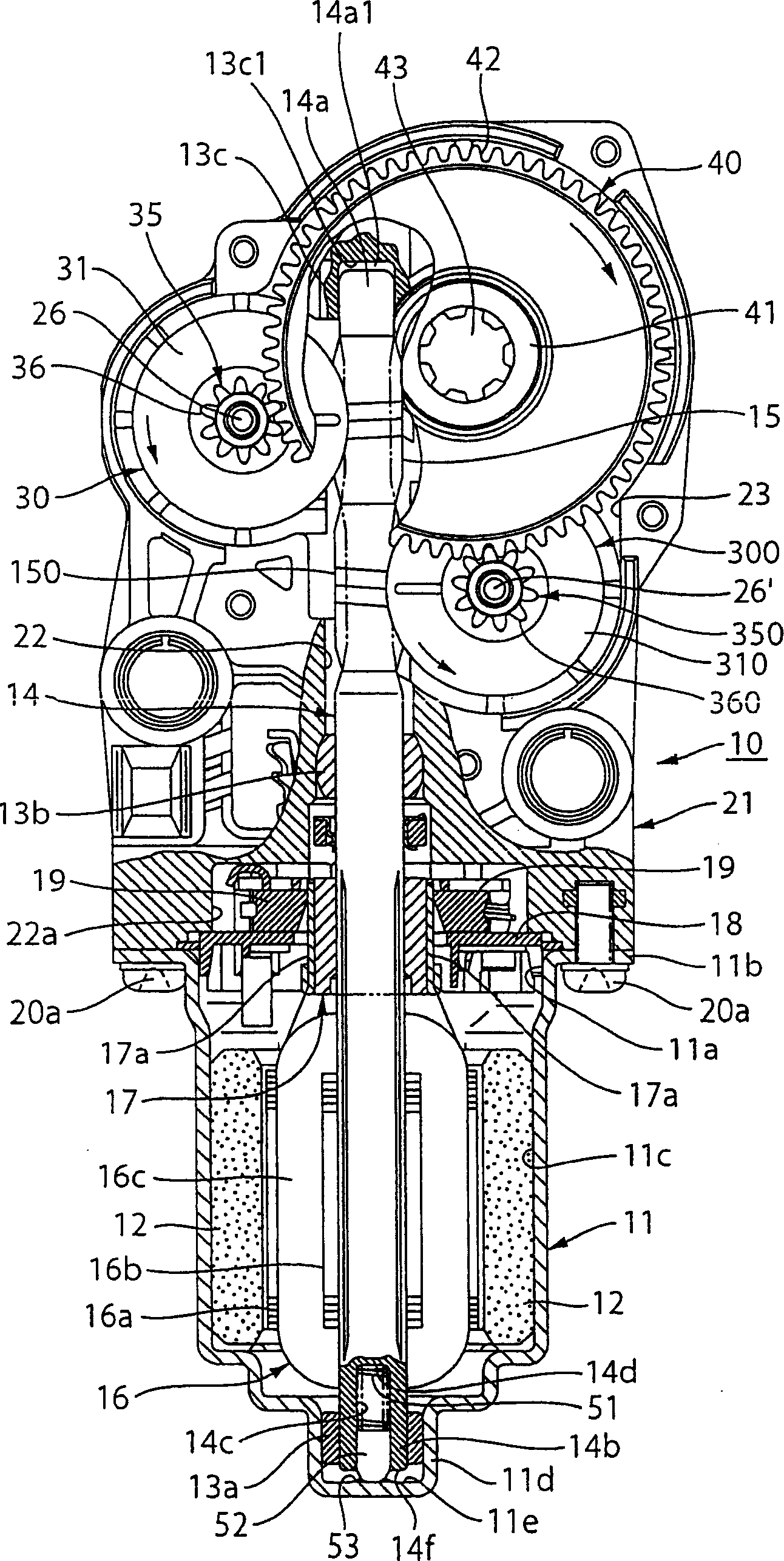
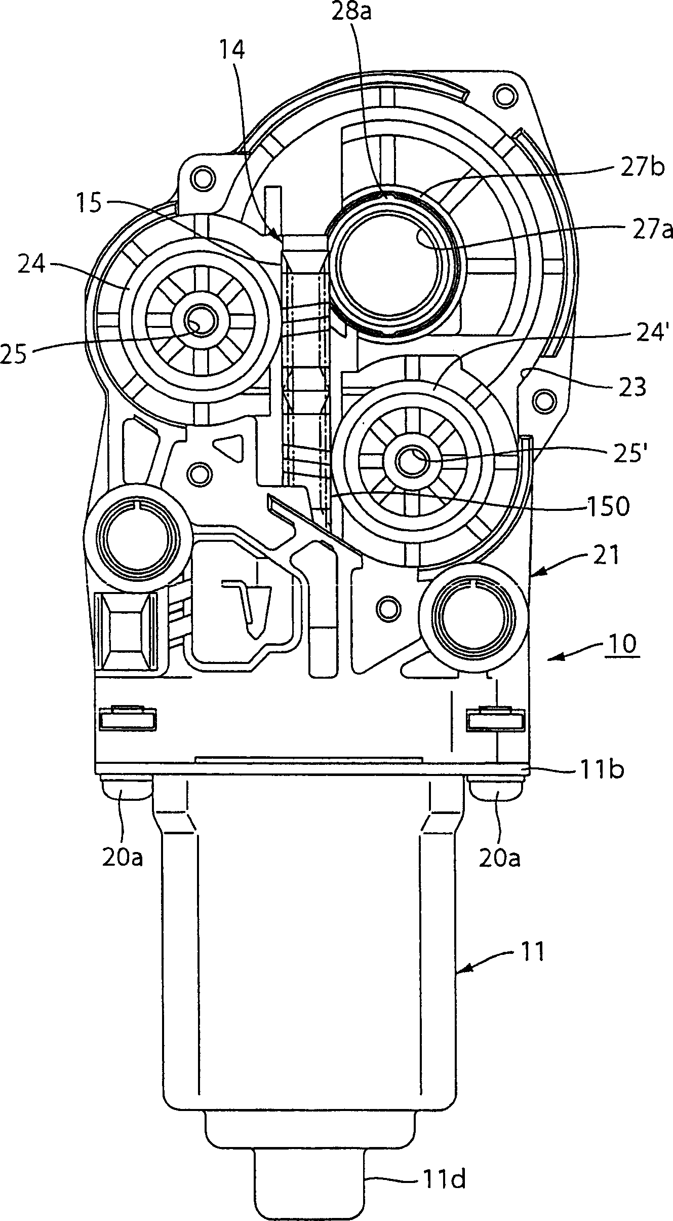
[0032] Fig. 1 is a plan view of a motor with a reduction mechanism according to an embodiment of the present invention; figure 2 is the sectional view of the motor; image 3 is the plan view of the motor after the gearbox of the motor is removed; Figure 4 It is an enlarged sectional view of the main part of the motor; Fig. 5 is a schematic diagram when the motor shaft used in the motor does not rotate; Image 6 is a schematic diagram when the motor shaft used in the motor rotates forward; FIG. 7 is a schematic diagram when the motor shaft used in the motor rotates reversely. In addition, a vehicle seat (electric seat 1 ) as shown in FIG. 8 for explaining a vehicle device having a conventional motor is also used here to explain the present invention.
[0033] Figure 1, figure 2 with image 3 As shown, a motor 10 for an electric seat with a reduction mechani...
PUM
 Abstract
Description
Claims
Application Information
PatSnap Eureka turns technology decisions into work you can execute. Powered by our Innovation Knowledge Graph, it runs expert workflows across engineering, life sciences, materials and intellectual property. Get your review-ready output in minutes.


