Energy-saving cooking pot with rotary gas

An energy-saving pot and screw technology, applied in cooking utensils, household appliances, applications, etc., can solve the problems of short contact time, energy loss and loss, small contact area, etc., and achieve low cost, high heat utilization rate, and large contact area. Effect

Inactive Publication Date: 2005-06-29
HUNAN UNIV
View PDF0 Cites 3 Cited by
  • Summary
  • Abstract
  • Description
  • Claims
  • Application Information

AI Technical Summary

Problems solved by technology

Most of the pots currently used are heat exchanged between the gas produced by the combustion of fuel materials and the outer surface of the pot and the fuel radiates light and heat to the outer surface of the pot to achieve the heating function. Because the outer surface

Method used


Image

  • Energy-saving cooking pot with rotary gas
  • Energy-saving cooking pot with rotary gas

Examples


Embodiment Construction

[0012] The present invention will be described in further detail below in conjunction with the accompanying drawings and specific embodiments.

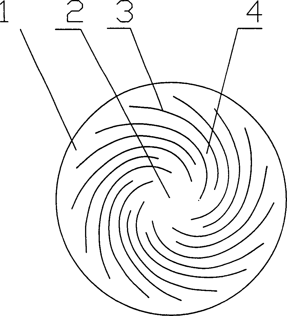
[0013] see figure 1 On the outer surface of the pot body 1 centering on the bottom center 2 of the pot body, there are spiral radial metal ribs 3 radiating involute left helically, the radial cross-section is triangular, and spiral smoke is formed between the spiral radial metal ribs 3 Road 4.

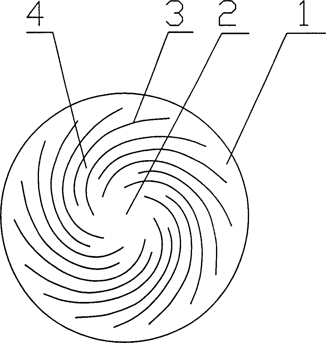
[0014] see figure 2 , on the outer surface of the pot body 1 centered on the bottom center 2 of the pot body, there are spiral radial metal ribs 3 radiating involute right helically, the radial cross-section is semicircular, and there are formed between the spiral radial metal ribs 3 Spiral flue 4.

[0015] When in use, the fire gas flow spirals up along the spiral flue 4 to generate a swirling heat flow, which prolongs the heat exchange time between the gas flow and the pot body 1 on the one hand, and on the other hand, presents a spiral ...


PUM


Abstract

The invention discloses a gas rotating energy conservation pot, wherein the external surface of the pot body is provided with helical radiation shape metallic ribs with pot bottom pole as the center, helical smoke conduits are formed between the metallic ribs. The pot has the advantages of longer time of contact in heat exchange, larger contact area, higher combustion gas heat utilizing rate, simpler structure, easy manufacture, and low cost.

Description

technical field [0001] The invention relates to a pot, in particular to a cyclone energy-saving pot. Background technique [0002] Cookware is a kind of necessities in people's life and plays an important role in people's life. Most of the pots currently used are heat exchanged between the gas produced by the combustion of fuel materials and the outer surface of the pot and the fuel radiates light and heat to the outer surface of the pot to achieve the heating function. Because the outer surface of the pot is smooth, the gas and the outer surface of the pot The contact time is short and the contact area is small during heat exchange, resulting in only about 15% of the thermal energy utilization rate of the fuel material, resulting in a large loss of energy loss. Contents of the invention [0003] The technical problem to be solved by the present invention is to provide a swirling gas energy-saving pot with longer contact time and larger ...

Claims


Application Information

Patent Timeline
IPC IPC(8): A47J27/00A47J27/02
Inventor 陈小林王祝盈谢中何仁生
Owner HUNAN UNIV
Why Eureka
Try Eureka