Self-wringing mop

A mop and handle technology is applied in the field of reverse locking devices, which can solve the problems of increasing processing cost and manufacturing cost, and achieve the effects of reducing manufacturing cost, low structure and simple cost.

Inactive Publication Date: 2005-07-06
CARL FREUDENBERG KG
View PDF1 Cites 0 Cited by
  • Summary
  • Abstract
  • Description
  • Claims
  • Application Information

AI Technical Summary

Problems solved by technology

In this self-squeezing mop, like the above-mentioned mop, the components of the reversing locking device must also be manufactured very precisely, which increases the processing and manufacturing costs.

Method used


Image

  • Self-wringing mop
  • Self-wringing mop
  • Self-wringing mop

Examples


Embodiment Construction

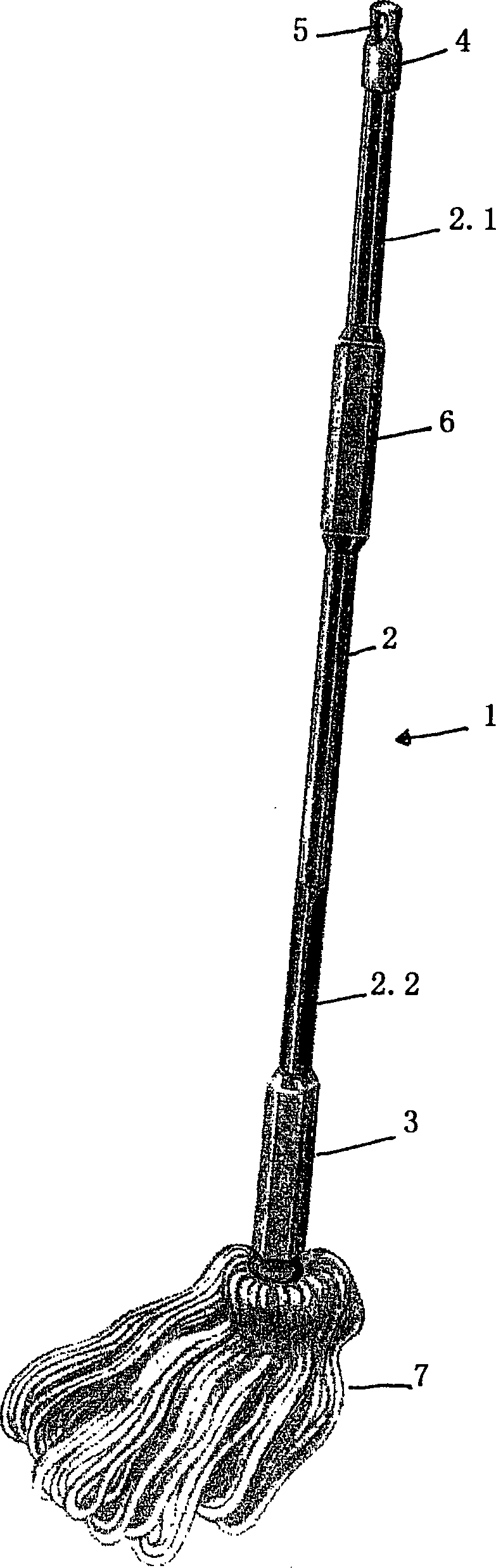
[0026] exist figure 1A self-squeezing mop 1 according to the invention can be seen in the figure. The self-wringing mop 1 according to the invention has a handle 2 and an actuating sleeve 3 arranged rotatably and axially displaceably on the handle 2 . On the upper end of the handle 2 there is a closure cap 4 with a ring 5 for hanging the mop 1 . A handle 6 arranged in the upper region of the handle 2 facilitates the handling of the mop 1 . The handle is preferably provided with ribs or ribs to prevent the hand from slipping. For this purpose, the handle can likewise have, for example, a polygonal, in particular octagonal, outer diameter. There is a mop head 7 at the lower end of the handle 2. In the embodiment shown, without loss of generality, the mop head consists of a cord-like element which is detachably fastened with its lower end to the lower end of the handle 2 and with its upper end to the lower end of the actuating sleeve 3 . In the embodiment shown, the actuatin...


PUM


Abstract

The invention relates to a self-squeezing mop (1), which has a handle (2), an operating sleeve (3) rotatably arranged on the handle (2), and a mop that can pass through the handle (2). ) and the operating sleeve (3) relatively rotate the mop head (7) of the cleaning element that is squeezed dry, and a mop head (7) that is used to fix the operating sleeve (3) on the handle (2) to prevent accidental Reversing anti-reversing locking device, this device includes a rib-shaped protrusion extending axially at least on the specified length (2.1) of the handle (2), and at least one rib extending radially inward from the operating sleeve The locking element (8.1) in the swivel area of ​​the rib-shaped protrusion presses against the wall of the operating sleeve (3) via the rib-shaped protrusion when the handle (2) is rotated in the locking direction and This forms a stop for the rib-shaped projection, whereas the locking element deflects the rib-shaped projection outward against the spring force when it is rotated in the direction of travel. According to the invention the handle ( 2 ) has a polygonal cross-section on the length ( 2.1 ), where the rib-shaped projections are formed by the axially extending edges ( 2.1.1 , 2.1.2 ) of the length ( 2.1 ) . Furthermore, the invention relates to a counter-rotating locking device of the above-mentioned type.

Description

technical field [0001] The invention relates to a self-squeezing mop, which has a handle, an operating sleeve rotatably arranged on the handle, and a mop head with cleaning elements, which can be rotated through the relative rotation between the handle and the operating sleeve. The wring cleaning element also has a reversing lock for securing the sleeve to the handle to prevent inadvertent reversing during wringing, the reversing locking being comprised of at least one defined limit on the mop. A rib-shaped protrusion extending axially on the length section and at least one locking member extending radially inward from the operating sleeve into the rotation area of ​​the rib-shaped protrusion, the locking member rotates in the locking direction when the handle When the passage rib-shaped projection presses against the wall of the actuating sleeve and thus forms a stop for the rib-shaped projection, on the other hand, when rotating in the direction of passage, the rib-shaped pr...

Claims


Application Information

Patent Timeline
Patent Type & Authority Applications(China)
IPC IPC(8): A47L13/142
CPCA47L13/142
Inventor U·丁格特
Owner CARL FREUDENBERG KG
Why Eureka
Try Eureka