Pivoting piston engine

A piston-type, piston-type technology, applied in the field of oscillating piston-type machinery, to achieve the effect of improving efficiency

Inactive Publication Date: 2005-07-13
赫伯特·许特林
View PDF1 Cites 14 Cited by
  • Summary
  • Abstract
  • Description
  • Claims
  • Application Information

AI Technical Summary

Problems solved by technology

Another disadvantage is that the output shaft

Method used


Image

  • Pivoting piston engine
  • Pivoting piston engine
  • Pivoting piston engine

Examples


Embodiment Construction

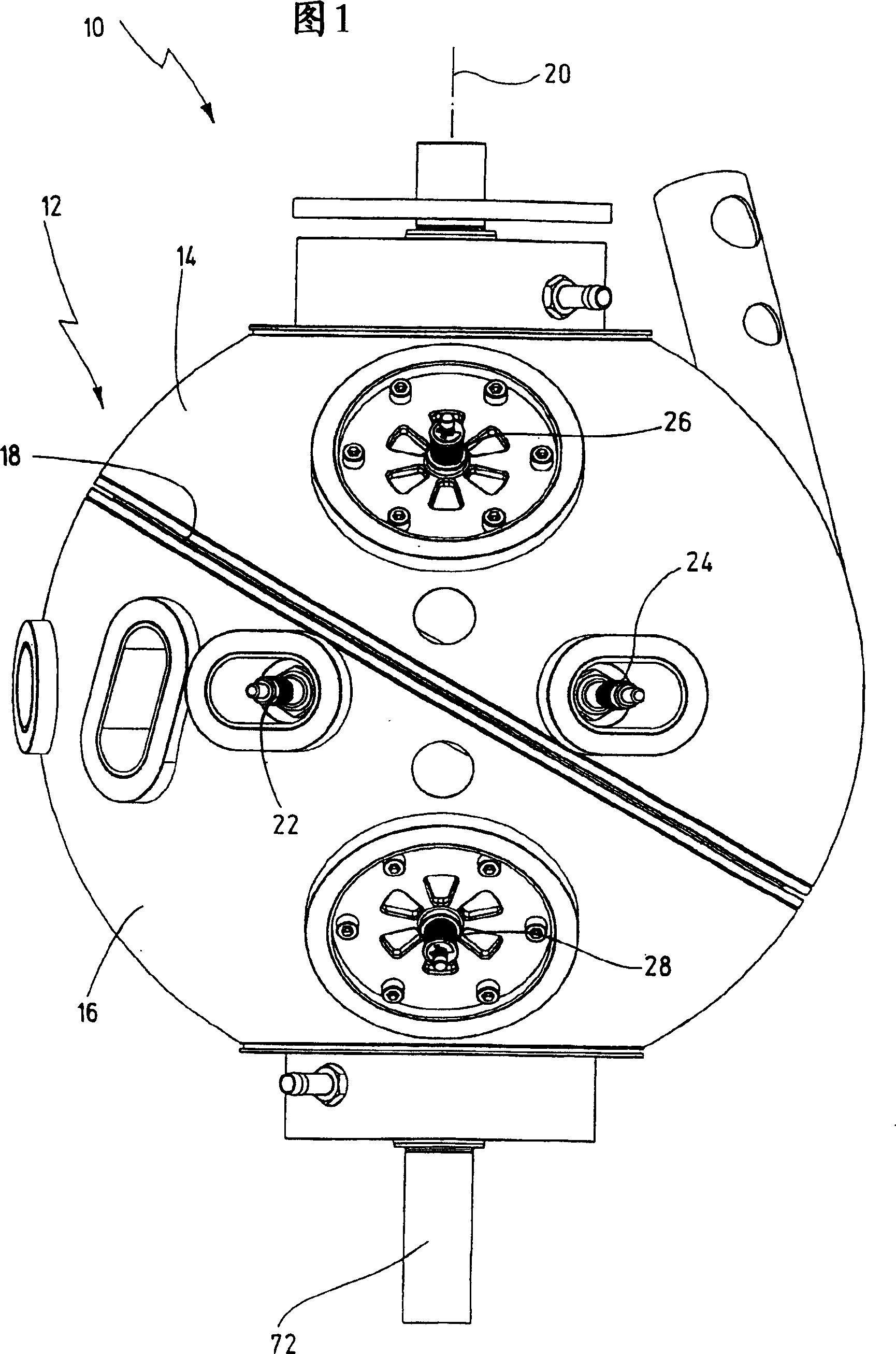
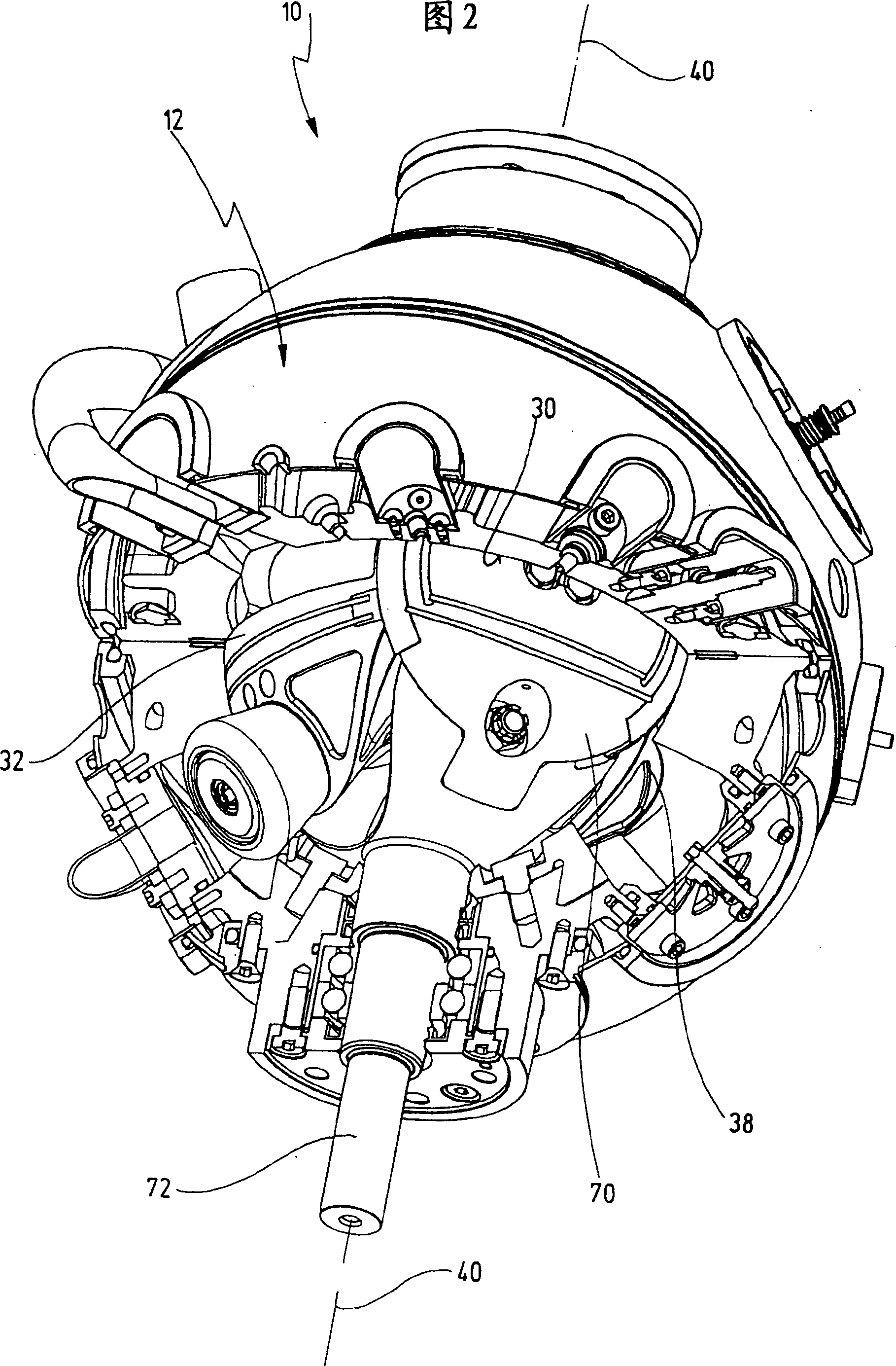
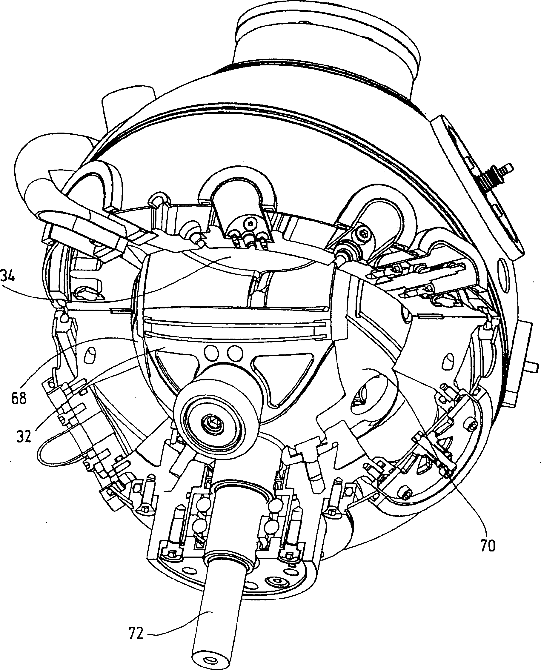
[0057] The design of the oscillating-piston machine generally designated 10 will be described in detail below with reference to FIGS. 1 to 9 . The oscillating piston machine 10 is used, for example and preferably, as an internal combustion engine.

[0058] The oscillating piston machine 10 has a housing 12 consisting of a first half shell 14 and a second half shell 16 .

[0059] The half-shells 14 and 16 are combined along a dividing line 18 which extends not vertically but obliquely with respect to the oscillating piston machine 10 (to be described later) and also to a line of symmetry 20 representing the axis of rotation of the pistons. of. The advantage of this oblique orientation of the boundary line 18 separating the half-shells 14 and 16 from each other is that the technical components located in the casing, such as cross joints and nozzles 22, 24 or valves 26, 28, can be more easily arranged. Arranged in a proper way, these components are not affected by the boundarie...


PUM


Abstract

The invention relates to an oscillating piston machine, the casing (12) of which has a spherical inner wall, and four pistons (32-38) are arranged in the casing, and they jointly rotate around a rotation axis (40), and each of the four pistons Two pistons diametrically opposed to the center of the housing form a rigid pair of pistons (32/36, 34/38) which can pivot about a common axis of oscillation perpendicular to the axis of rotation (40) ( 42) Swing back and forth in reverse, the two piston pairs are arranged through the cross joint relative to the swing axis, so that the two pistons of the two piston pairs face each other with their working surfaces, so as to form a working surface between the working surfaces. Cavities (48, 50), each pair of pistons has a supporting section (52, 56) for supporting the pair of pistons on the swing axis, and each of the two pistons of the pair of pistons has a side wall section (54) for forming them respectively A lateral boundary of a working chamber. The support section and the side wall section are designed in one piece and are arranged on the same side of the respective piston pair.

Description

technical field [0001] The invention relates to an oscillating piston machine (Schwenkkolbenmaschine), which has a casing with a substantially spherical casing inner wall, in which four pistons are housed, which together revolve around a shaft approximately in the center of the casing. The axis of rotation rotates, and two of the four pistons generally diametrically opposed to the center of the housing form a rigid pair of pistons that are oscillating about a common path extending generally perpendicular to the axis of rotation The axis swings back and forth in opposite directions, wherein the two piston pairs are arranged via a cross joint relative to the swing axis, so that the two pistons of the two piston pairs each face each other with their piston working surfaces, so that between the piston working surfaces A working chamber is formed between them, and each pair of pistons has a support section for supporting the pair of pistons on the pivot axis, and each of the two pi...

Claims


Application Information

Patent Timeline
IPC IPC(8): F01C9/00F01C21/08
CPCF01C9/005F01C21/0809F01C21/0836
Inventor 赫伯特·许特林
Owner 赫伯特·许特林
Why Eureka
Try Eureka