Pancake compressor

An opposed type, compressor technology, applied in the direction of pump devices, mechanical equipment, machines/engines, etc., can solve the problem of low efficiency of engine use, achieve efficient use and suppress vibration

Active Publication Date: 2005-07-13
HITACHI LTD
View PDF2 Cites 14 Cited by
  • Summary
  • Abstract
  • Description
  • Claims
  • Application Information

AI Technical Summary

Problems solved by technology

Therefore, the following problem arises: it is necessary to use an engine with a driving torque to overcome this load, but a pair of pistons only reaches the top dead center once in each revolution, and such a large driving torque is not required for the rest of the stroke, so Inefficient use of the engine

Method used


Image

  • Pancake compressor
  • Pancake compressor
  • Pancake compressor

Examples


no. 4 approach

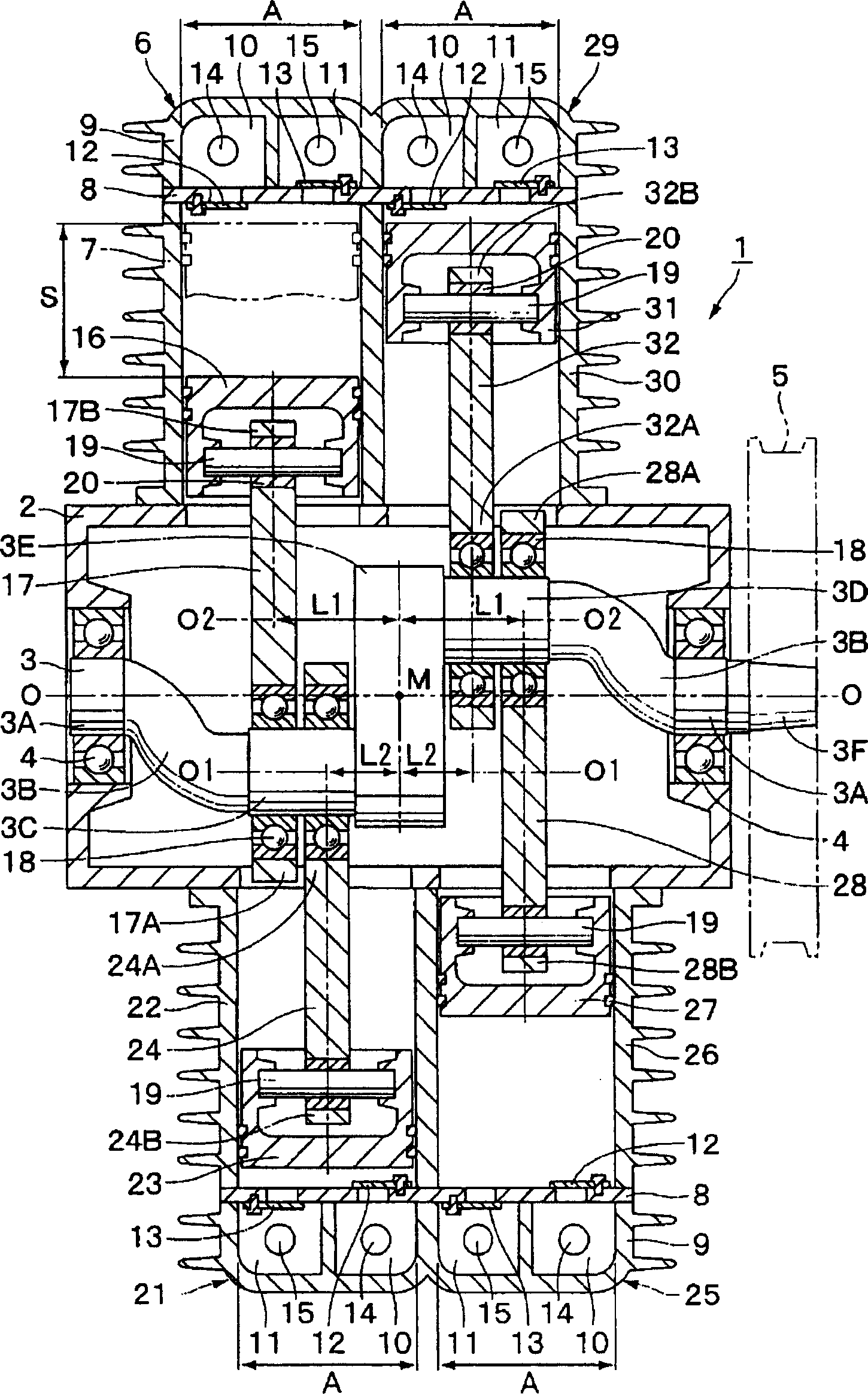
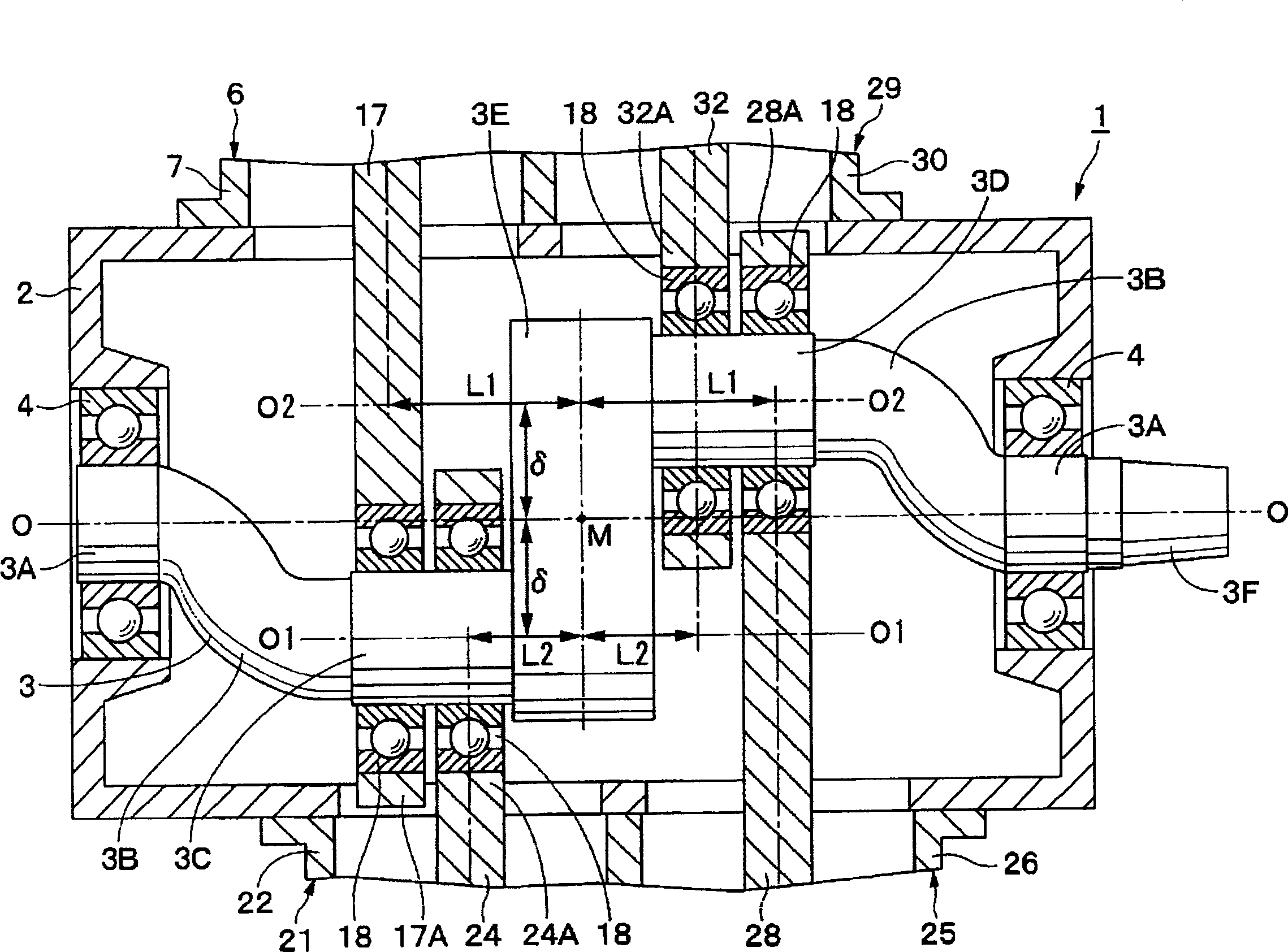
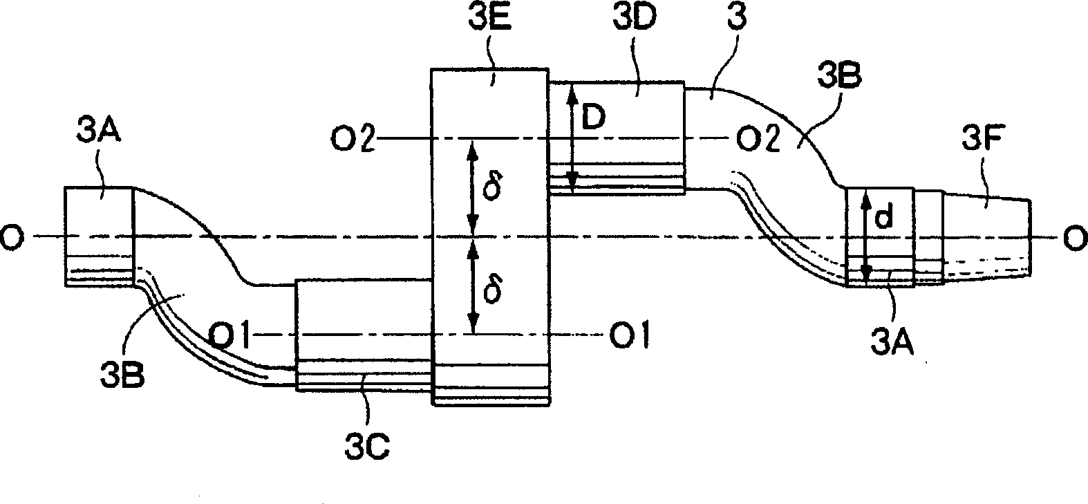
[0094] then, Figure 14 The fourth embodiment of the present invention is shown, and this embodiment is characterized in that it is applied to a six-cylinder compressor. In addition, in this embodiment, the same code|symbol is attached|subjected to the same structural element as the said 1st Embodiment, and the description is abbreviate|omitted.

[0095] 61 is a horizontally opposed six-cylinder air compressor, and this air compressor 61 is composed of a crankcase (not shown), a crankshaft 3, first to fourth compression units 6, 21, 25, 29, and the fifth and sixth compression parts 62 and 66 described later.

[0096] Here, the fifth compression unit 62 is formed substantially in the same manner as the compression unit 6 , and has a cylinder 63 , a piston 64 , and a connecting rod 65 . In addition, the sixth compression unit 66 is disposed on the opposite side in the radial direction from the fifth compression unit 62 , and has a cylinder 67 , a piston 68 , and a connecting r...


PUM


Abstract

The present invention provides a horizontally opposed compressor that sufficiently secures the stroke of the piston, arranges each compression section in a balanced manner, is small in size, and has little vibration. The compression part (6, 25) is connected to the eccentric part (3C, 3D) at a position away from the middle position (M) of the crankshaft (3) by the dimension (L1), and the inner diameter (A) of the cylinder (7, 26) and the piston The strokes (S) of (16, 27) are equal. In addition, the compression part (21, 29) is connected to the eccentric part (3C, 3D) at a distance (L2) from the middle position (M), and the inner diameter (A) of the cylinder (22, 30) and the piston (23, 31 ) stroke (S) equal. Accordingly, a balancer or the like is unnecessary, and the compressor can be reduced in size and weight, and vibration can be reduced. Furthermore, since the respective connecting rods (17, 24, 28, 32) can be connected to the crankshaft (3) with the axial positions of the pistons slightly shifted, the stroke (S) can be sufficiently ensured even in a compact arrangement.

Description

technical field [0001] The present invention relates to horizontally opposed compressors suitable for use in eg air, refrigerant etc. compression or vacuum pumps and the like. Background technique [0002] Generally, in a horizontally opposed compressor, a plurality of cylinders are arranged to face each other in the radial direction of the crankshaft, and a horizontally opposed reciprocating mechanism is used in such a compressor (for example, refer to Patent Document 1). [0003] [Patent Document 1] (Japanese) Unexamined Patent Publication No. 49-57208 [0004] Such a conventional reciprocating mechanism is composed of a crankshaft rotatably provided on a supporting member such as a crankcase via a bearing, and two compressors that are driven by the crankshaft and compress air, refrigerant, and the like. [0005] Here, two eccentric portions having a phase difference of 180° are formed on the crankshaft, and these eccentric portions are separated (eccentrically) at equal ...

Claims


Application Information

Patent Timeline
Patent Type & Authority Applications(China)
IPC IPC(8): F04B27/02F04B27/12F04B35/01F04B41/02F04B41/06
Inventor 杉本正则
Owner HITACHI LTD
Why Eureka
Try Eureka