Supercharge Your Innovation With Domain-Expert AI Agents!

Disk player

A technology for players and drive trays, which is applied in the direction of instruments, record carrier structural parts, and reduction of physical parameters of the carrier. Small, vibration-reducing effect

Inactive Publication Date: 2005-07-13
FUNAI ELECTRIC CO LTD
View PDF0 Cites 0 Cited by
  • Summary
  • Abstract
  • Description
  • Claims
  • Application Information

AI Technical Summary

Problems solved by technology

[0009] In the configuration described, since the disturbance of the focus servo performance is large, it takes a certain time for the focusing of the objective lens OL with respect to the disk D, and thus delays the reading speed

Method used


Image

  • Disk player
  • Disk player
  • Disk player

Examples


Embodiment Construction

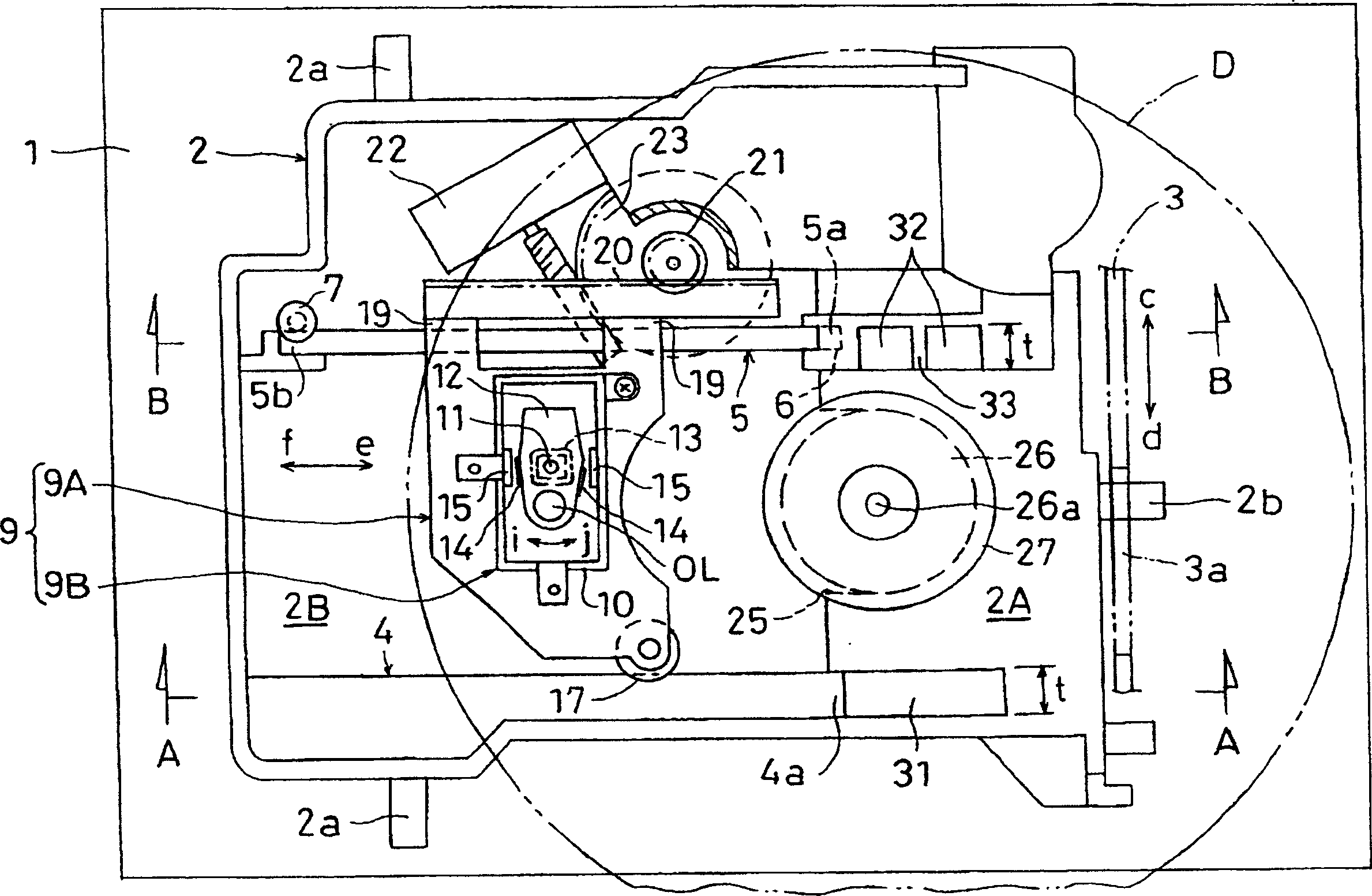
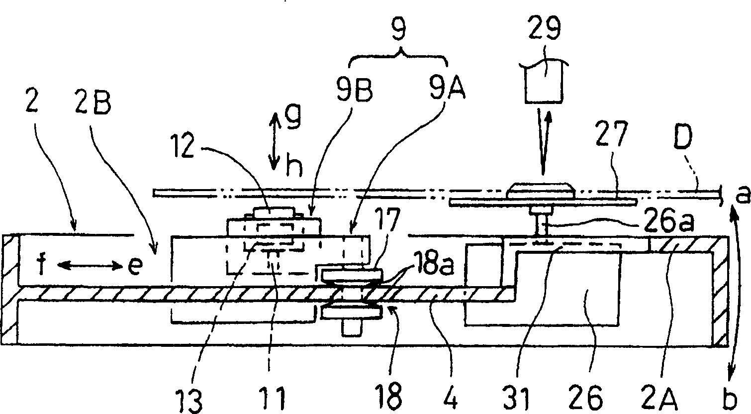
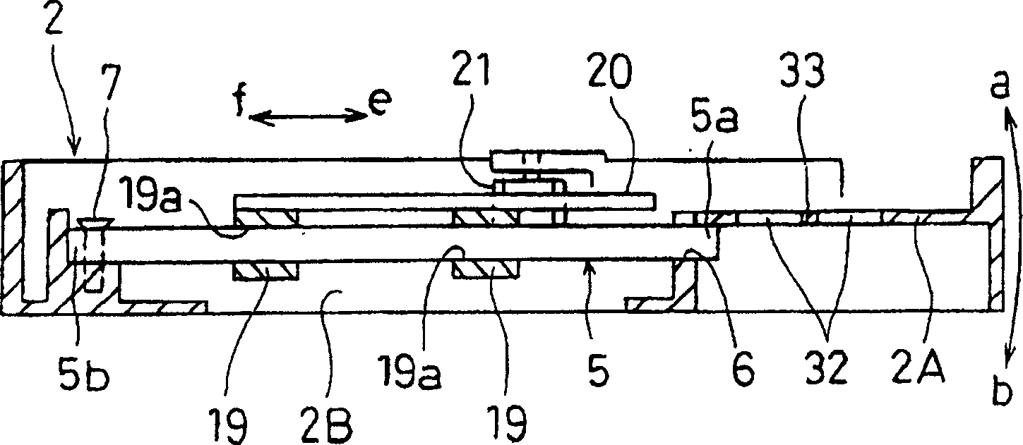
[0037] Figure 1-4 Shows a disk player according to an embodiment of the present invention. Vibration damping holes 31 and 32 are respectively penetratingly provided in the cover plate 2A substantially between the spindle motor fixing recessed groove 25 of the cover plate 2A and the guide shaft 5 . The damping hole 31 is formed to extend from the front end 4 a of the guide rail 4 in the forward direction e, and has the same width as the guide rail 4 . Meanwhile, the damping hole 32 is formed to extend in the forward direction from near the front end 5 a of the guide shaft 5 and has approximately the same width as the damping hole 31 . A reinforcement beam crossing an approximately central portion of the damping hole 32 on the guide shaft side is integrally formed with the cover plate 2A. Since except as stated, this configuration is the same as Figure 5-9 The configurations are substantially the same, and the same parts will be denoted by the same reference numerals, and de...


PUM


Abstract

A cover plate is integrally formed on the front side of the drive tray. As the drive tray moves upwards, the discs are mounted on the turntable. The disk is rotated at high speed by the spindle motor, the optical pickup is reciprocated along the guide rail and the guide shaft, and the lens holder is moved in the focusing direction and the tracking direction. Laser light is projected on the disc via an objective lens to read information recorded on the disc. Vibration damping holes are respectively penetratingly provided in the cover plate between the spindle motor fixing concave groove of the cover plate and the guide rail, and between the concave groove and the guide shaft.

Description

technical field [0001] The present invention relates to a disc player for realizing duplication, recording or deletion of an optical disc or magnetic disc (hereinafter referred to as disc) such as DVD. Background technique [0002] Conventionally, a technique related to a disk player as shown in, for example, JP-A-293369 is known. refer to Figure 5-9 A description of such an instance is given. In this disk player, a drive tray 2 made of synthetic resin is arranged in a housing 1 in such a manner that it moves upwards a and Movement in the direction of down b. A cam shaft 2b protrudingly provided on the front surface of the drive tray 2 is fitted in a cam hole 3a of a cam plate 3 movable in leftward c and rightward d directions. A cover plate 2A is integrally formed on the front side of the drive tray 2 , and an accommodating recess 2B is formed on a side portion of the drive tray 2 positioned behind the cover plate 2A. One side of the accommodation recess 2B is formed a...

Claims


Application Information

Patent Timeline
IPC IPC(8): G11B33/02G11B7/085G11B21/02G11B25/04G11B33/08G11B33/14
CPCG11B7/08582G11B33/08
Inventor 岩朝洋昭古贺未青
Owner FUNAI ELECTRIC CO LTD
Features
  • R&D
  • Intellectual Property
  • Life Sciences
  • Materials
  • Tech Scout
  • Unparalleled Data Quality
  • Higher Quality Content
  • 60% Fewer Hallucinations
Learn More