Fabric antenna for tags

A fabric, antenna technology, applied in the field of RFID transponders, can solve problems such as increasing the minimum size

Inactive Publication Date: 2005-07-13
KONINKLIJKE PHILIPS ELECTRONICS NV
View PDF0 Cites 8 Cited by
  • Summary
  • Abstract
  • Description
  • Claims
  • Application Information

AI Technical Summary

Problems solved by technology

However, including a larger antenna in an RF tag has the und...

Method used


Image

  • Fabric antenna for tags
  • Fabric antenna for tags
  • Fabric antenna for tags

Examples


Embodiment Construction

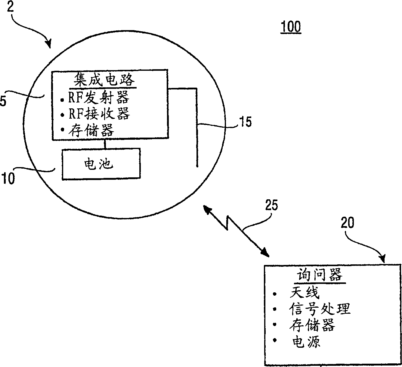
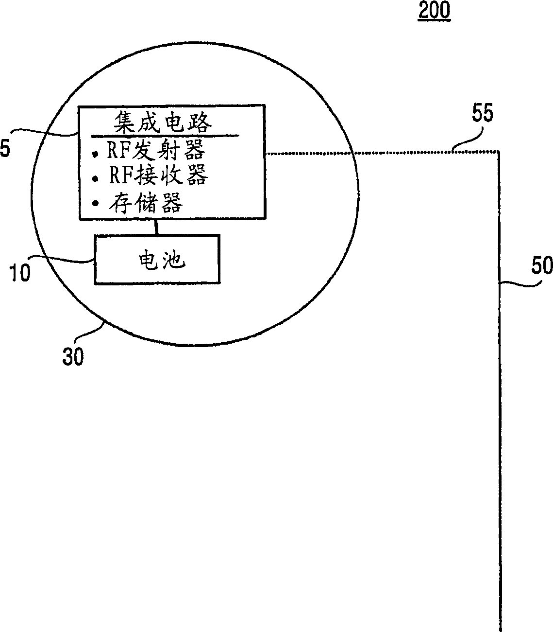
[0015] refer to figure 1 , described is an example RFID system 100 environment suitable for use with RF tags having fabric antennas of the present teachings. in particular, figure 1 An RF tag 2 and an RF interrogator 20 associated with the RF tag 2 are depicted. The RF tag 2 includes an exemplary integrated circuit 5 . Exemplary integrated circuit 5 includes, for example, an RF transmitter for transmitting signals (eg, signal 25 ), an RF receiver for receiving signals 25 , and memory for storing data. In the case of an active tag, a battery 10 is provided in the RF tag 2 to power the integrated circuit 5 . In instances where the RF tag 2 is a passive tag, the battery 10 is not included in the RF tag 2 . As will be apparent in the description below, the present teachings can be extended to encompass both active and passive tags. The RF tag 2 illustrates an RF tag comprising an antenna 15 in a casing enclosing the RF tag 2 . An internal antenna 15 is coupled to the integra...


PUM


Abstract

A method and system for providing an RFID transponder (200) with a fabric antenna (50). The system includes a radio frequency (RF) transponder having a housing (30) in which RF circuitry (5) is encapsulated and a fabric antenna coupled to the RF circuitry. A method of manufacturing a radio frequency (RF) transponder includes the steps of enclosing an RF circuit in a housing, forming a fabric antenna, and coupling the fabric antenna to the RF circuit.

Description

technical field [0001] The present invention relates to radio frequency (RF) transponders, such as radio frequency identification (RFID) transponders, and more particularly to a method and system for providing RFID transponders with fabric antennas. Background technique [0002] RFID systems are useful in a wide variety of applications including, for example: secure access, retail automation, inventory control, identification, and manufacturing automation. An RFID system typically includes: an RFID transponder (hereinafter an RF tag) having a semiconductor memory and an antenna; and an RFID interrogator comprising a transmitter-receiver unit for interrogating the RF tag over a wireless communication link. The RF tag detects the interrogation signal and sends an encoded response signal to the interrogator. RF tags can be active or passive. Active RF tags include an internal battery source to operate the active RF tag's associated electronics, while passive RF tags do not ha...

Claims


Application Information

Patent Timeline
IPC IPC(8): A41D1/00G01S19/35G06K19/04G06K19/07G06K19/077H01Q1/27H01Q1/38H04B1/59
CPCA41D1/002G06K19/027G06K19/04G06K19/07749G06K19/07758H01Q1/273G06K19/077
Inventor C·R·范希尔登G·马马罗波洛斯
Owner KONINKLIJKE PHILIPS ELECTRONICS NV
Why Eureka
Try Eureka