Long-span rotor system and gas turbine generator set

A gas turbine, long-span technology, applied in the direction of gas turbine devices, machines/engines, mechanical equipment, etc., can solve the problems of unstable operation of the rotor system, complex thrust bearing structure, size limitation, etc., to achieve good heat dissipation, low cost, The effect of low manufacturing cost

Pending Publication Date: 2020-03-06
TECH XANADU OF RESONATORY SOLAR SYSTD CO LTD +1
View PDF0 Cites 2 Cited by
  • Summary
  • Abstract
  • Description
  • Claims
  • Application Information

AI Technical Summary

Problems solved by technology

[0005] In order to solve the above technical problems, the object of the present invention is to provide a long-span rotor system and a gas turbine generator set. In the present invention, the two fulcrums are placed at both ends of the rotating shaft, so that the balance of the rotating shaft is better, and the operation stability of the rotor system is improved. Good; at the same time, the invention can solve the size limitation of the tail of the rotating shaft, solve the problems of unstable operation and serious vibration of the rotor system, and solve the technical problems of the existing one-piece thrust bearing with complex structure and easy damage

Method used


Image

  • Long-span rotor system and gas turbine generator set
  • Long-span rotor system and gas turbine generator set
  • Long-span rotor system and gas turbine generator set

Examples


Embodiment 1

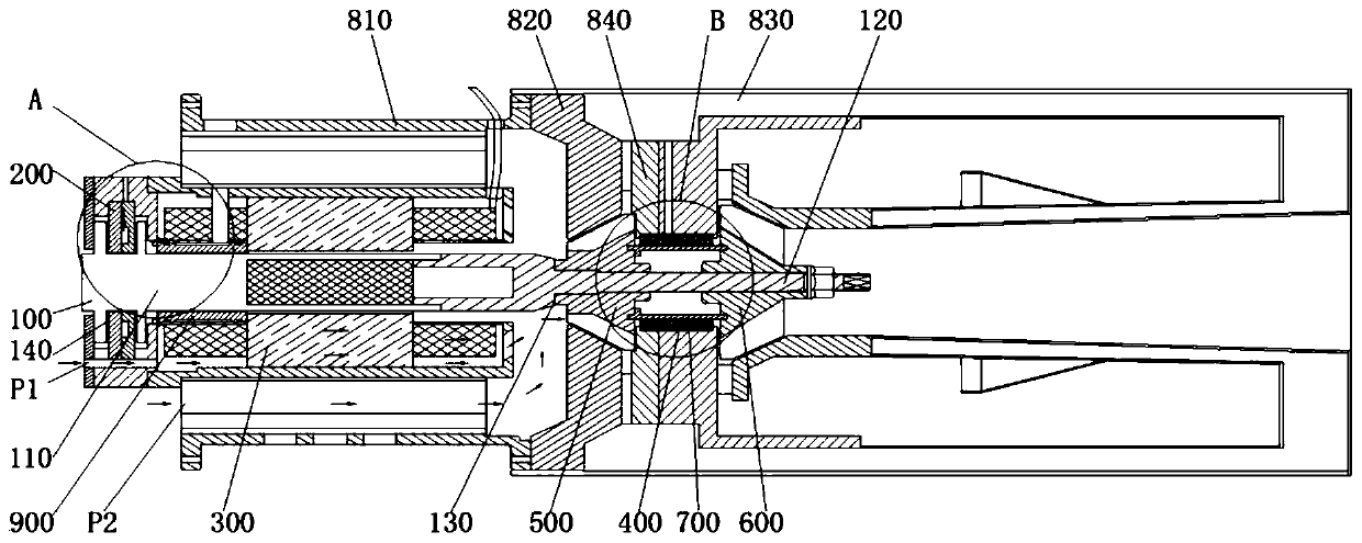
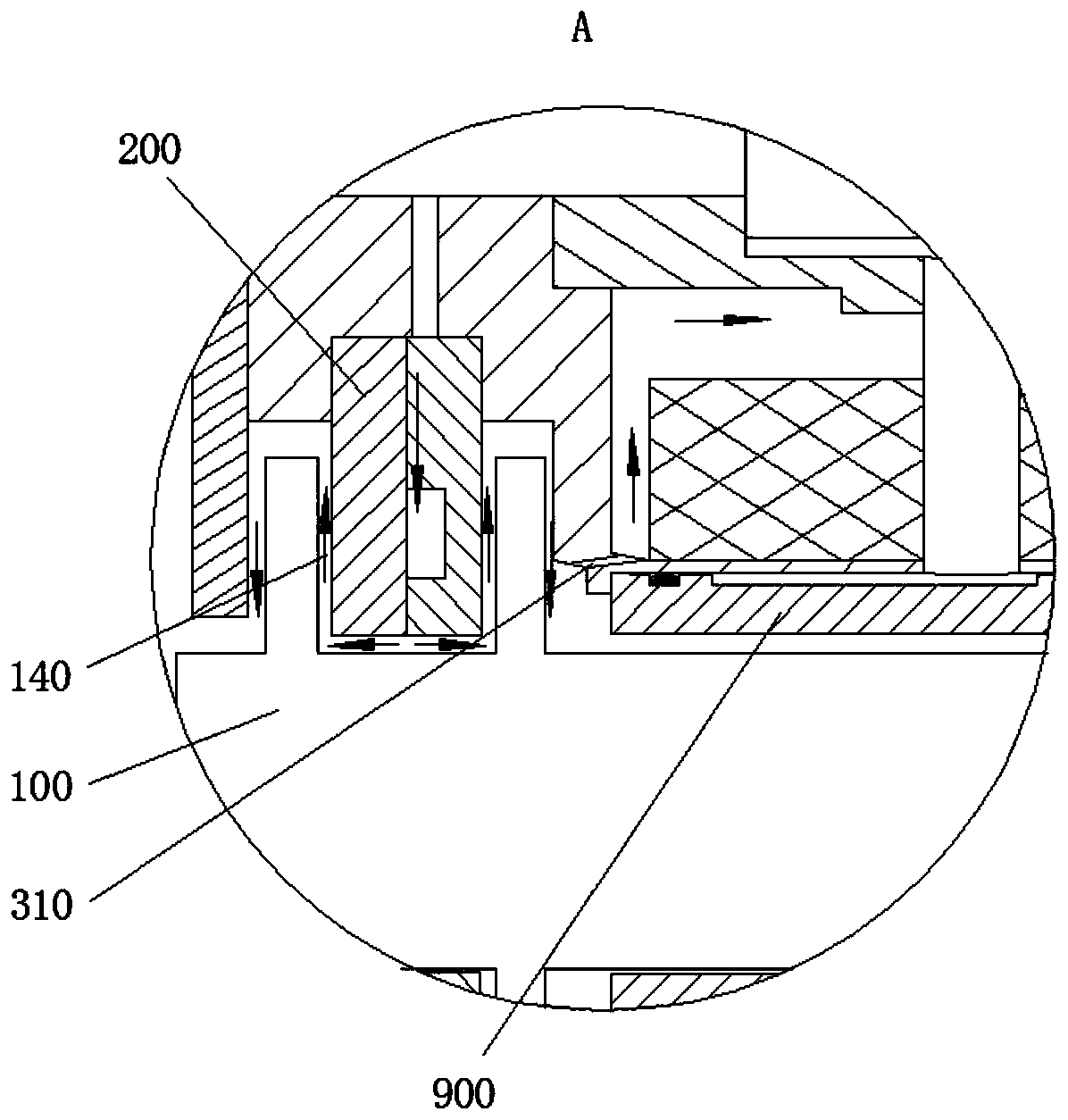
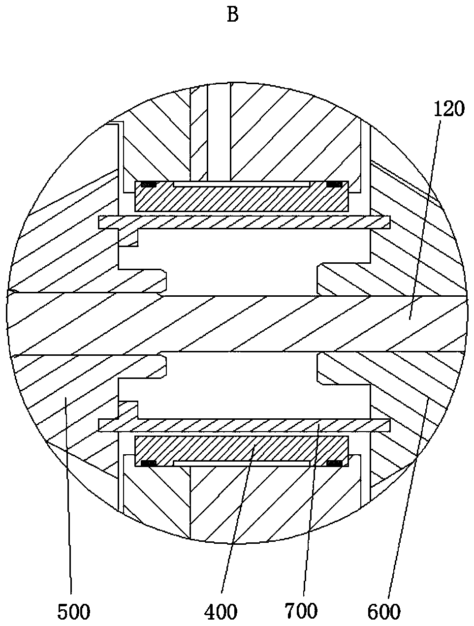
[0042] Such as figure 1 As shown, it includes a rotating shaft 100, and the rotating shaft 100 includes an integrally formed first shaft segment 110 and a second shaft segment 120, the diameter of the first shaft segment 110 is larger than the diameter of the second shaft segment 120, the first shaft segment 110 and the second shaft segment A stepped surface 130 is formed at the transition of the shaft section 120;

[0043] Among them, the thrust bearing 200, the first radial bearing 900, and the motor 300 are sequentially arranged on the first shaft section 110, and the compressor 500, the second radial bearing 400 and the turbine 600 are sequentially arranged on the second shaft section 120. One end of the machine 500 is in contact with the stepped surface 130 .

[0044] In the rotor system of the present invention, the rotating shaft 100 is supported by the bearings at both ends (the first radial bearing 900 and the second radial bearing 400 ), so that the force is uniform...

Embodiment 2

[0060] The first radial bearing 900 and the thrust bearing 200 in the first embodiment can also be set as an integrated bearing, and the thrust plate is set as one. The one-piece bearing is an integrated air bearing, which not only has the function of radial support, but also has the function of axial support.

[0061] Such as Figure 4 , 5 As shown, the integrated bearing in this embodiment includes: a first bearing body, a thrust plate, and a second bearing body; the thrust plate is fixedly connected or integrally formed with the rotating shaft 100; both the first bearing body and the second bearing body are sleeved on the rotating shaft And located on both sides of the thrust plate; the first bearing body has a radial bearing part and a thrust bearing part integrally formed, the radial bearing part and the rotating shaft 100 have a predetermined radial clearance in the radial direction, the thrust bearing part and the thrust plate on the shaft The second bearing body and ...


PUM


Abstract

The invention provides a long-span rotor system and a gas turbine generator set. The rotor system comprises a rotating shaft which is of an integrally formed structure. A thrust bearing, a first radial bearing, a motor, a gas compressor, a second radial bearing and a turbine are successively arranged on the rotating shaft. In the rotor system, two supporting points (the first radial bearing and the second radial bearing) are placed at two ends of the rotating shaft, separately, so that the rotating shaft is better in equilibrium and the rotor system is good in operating stability. The long-span rotor system can solve the problems of dimensional limit of the tail of the rotating shaft and unstable operation and severe vibration of the rotor system.

Description

technical field [0001] The invention relates to the technical field of rotor dynamics, in particular to a long-span rotor system and a gas turbine generator set. Background technique [0002] In the technical field of micro gas turbine power generation, a micro gas turbine generating set usually includes a coaxially installed generator and a micro gas turbine. Specifically, a micro gas turbine mainly includes three major components: a compressor, a combustion chamber and a turbine. After the air enters the compressor, it is compressed into high-temperature and high-pressure air, which is then supplied to the combustor and mixed with fuel for combustion. The high-temperature and high-pressure gas generated expands in the turbine to do work, driving the turbine to rotate, and then drives the generator to generate electricity. Since the magnetic components and coil windings in the generator are not resistant to high temperatures, the generator cannot be installed on the hot en...

Claims


Application Information

Patent Timeline
Patent Type & Authority Applications(China)
IPC IPC(8): F02C7/20F02C7/32F02C7/06F02C6/00
CPCF02C6/00F02C7/06F02C7/20F02C7/32
Inventor 靳普刘慕华
Owner TECH XANADU OF RESONATORY SOLAR SYSTD CO LTD
Why Eureka
Try Eureka