
Horizontal lifted underwater robot driven by temperature differential energy

An underwater robot and vertical lifting technology, applied to underwater ships, underwater operating equipment, motor vehicles, etc., can solve problems such as limited operating time

Active Publication Date: 2005-07-27
TIANJIN UNIV
View PDF0 Cites 9 Cited by
  • Summary
  • Abstract
  • Description
  • Claims
  • Application Information

AI Technical Summary

Problems solved by technology

Their main disadvantage is that due to energy constraints, the operating time is limited, and it is difficult to operate in a specific sea area for a long time

Method used


Image

  • Horizontal lifted underwater robot driven by temperature differential energy

Examples


Embodiment Construction

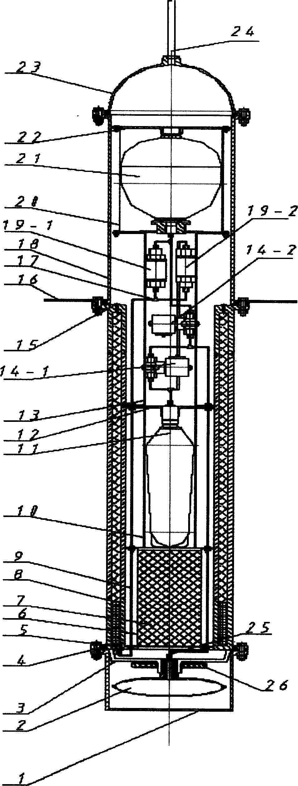
[0008] The structural principles of the present invention will be further described below through embodiments and with reference to the accompanying drawings. The pressure-resistant and sealed part of the underwater robot is composed of an outer skin bag protection shell 1, a sealed chassis 3, a heat engine working chamber 8, and a sealed cylindrical shell 18, and the parts are sealed by O-ring seals. For this embodiment, the accumulator 21 is a diaphragm accumulator with a working volume of 2L and a working pressure of 10Mpa. The working pressure of solenoid valve 14 and check valve 19 is 1.5Mpa. The thermal engine working chamber 8 of the underwater robot mainly plays a sealing role as a part of the pressure-resistant shell. In this embodiment, the temperature difference driven vertical lift underwater robot is designed to work in a water depth of 100 meters, with a water surface temperature of 20°C and a water depth of 100 meters with a temperature of about 10°C. The work...


PUM


Abstract

A temp difference energy driven underwater robot able to vertically float up or sink down is composed of external and internal leather bags, protecting casing consisting of sealed bottom, sealed cylinder, sealed spherical front end and working chamber of heat machine, electromagnetic valves, check valves and energy accumulator. Said working chamber is respectively connected via forward and backward check valves to energy accumulator and internal leather bag. Two check valves are also communicated to external leather bag.

Description

technical field [0001] The invention belongs to electromechanical integration, and in particular relates to an underwater robot that can be driven vertically up and down depending on temperature difference. technical background [0002] In order to protect the marine environment and efficiently utilize marine resources, marine exploration is essential. It is far from enough to rely solely on manpower for the detection of the ocean, and it largely relies on marine detection tools. In recent years, due to the need for the development of marine resources and the urgent need for monitoring the marine environment, many developed countries in the world have continuously strengthened or updated the marine environment monitoring systems in the sea areas under their jurisdiction and the survey and monitoring methods for the marine environment and resources in the world's common sea areas. On a large scale, all platform systems that can monitor the under...

Claims


Application Information

Patent Timeline
IPC IPC(8): B63C11/00B63G8/00B63H19/00
Inventor 王树新王延辉侯圣智张海根张大涛
Owner TIANJIN UNIV
Learn More