Liquid crystal displaying device with adjustable visual angle

A liquid crystal display and viewing angle technology, applied in static indicators, instruments, nonlinear optics, etc., can solve the problems of production and operation difficulty, and achieve the effects of favorable development and application, convenient operation, and simplified structure

Active Publication Date: 2005-07-27
AU OPTRONICS CORP
View PDF4 Cites 17 Cited by
  • Summary
  • Abstract
  • Description
  • Claims
  • Application Information

AI Technical Summary

Problems solved by technology

[0006] Although the above-mentioned liquid crystal display with adjustable viewing angle allows users to adjust the light transmittance accordi

Method used


Image

  • Liquid crystal displaying device with adjustable visual angle
  • Liquid crystal displaying device with adjustable visual angle
  • Liquid crystal displaying device with adjustable visual angle

Examples


Embodiment Construction

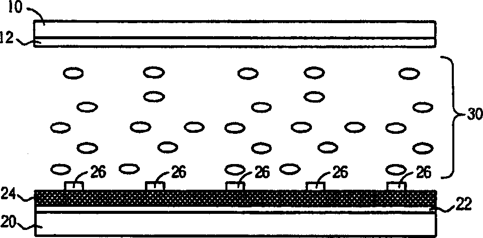
[0025] Please refer to figure 1 , figure 1 It is a schematic cross-sectional view of a liquid crystal display with an adjustable viewing angle according to the present invention. Such as figure 1 As shown, the liquid crystal display with adjustable viewing angle of the present invention includes two parallel substrates 10 and 20 , and a liquid crystal layer 30 filled between the substrates 10 and 20 . In a preferred embodiment of the present invention, the substrate 10 is a color filter substrate, which includes a plurality of red filters, green filters, blue filters and black matrix structures (not shown in the figure) , so that light can penetrate it to produce three primary colors such as red, green and blue, and then form a color image. The substrate 20 is a thin film transistor substrate, which includes elements such as thin film transistors arranged in an array, capacitors, scanning lines and signal lines (not shown in the figure) vertically interlaced to drive pixel ...


PUM


Abstract

A liquid crystal display with adjustable angle consists of the first and the second base plate, liquid crystal layer, the first and the second sheared electrode, a picture element electrode, and an insulation layer between the picture element and the second sheared electrode. It is featured as providing a driving voltage at picture element by the display to have the first shear electrode earthed and the second one suspension-jointed for providing a narrow visual angle mode and applying the same way to have the second sheared electrode earthed and the first one suspension-joined for providing a wide visual angle mode.

Description

technical field [0001] The invention relates to a liquid crystal display with an adjustable viewing angle, in particular to a liquid crystal display with an adjustable viewing angle which facilitates switching between two modes of a wide viewing angle and a narrow viewing angle. Background technique [0002] As the size of liquid crystal displays gradually increases, conventional twisted nematic type (TN type) liquid crystal displays generally have limitations in viewing angles, that is, images can only be seen from certain angles. In order to improve the limitation of the viewing angle of the liquid crystal display, so that users can watch clear and undistorted images from all angles, there have been many discussions about expanding the viewing angle in the prior art, such as attaching a viewing angle compensation film (viewing angle compensation film), forming different liquid crystal pre-tilt angle directions (pre-tilt angle direction) in a pixel area, and even the propos...

Claims


Application Information

Patent Timeline
IPC IPC(8): G02F1/133G02F1/1335G02F1/136
Inventor 吴明洲林永伦蔡孟璋陈伯纶
Owner AU OPTRONICS CORP
Why Eureka
Try Eureka