Spherical microchannel board and production thereof
A micro-channel plate and flat technology, which is applied in cold cathode manufacturing, electrode system manufacturing, discharge tube/lamp manufacturing, etc., can solve the problems of unusable flat micro-channel plates, achieve a stable and reliable preparation method, expand the scope of application, Simple and feasible effect of the process route
- Summary
- Abstract
- Description
- Claims
- Application Information
AI Technical Summary
Problems solved by technology
Method used
Image
Examples
Embodiment 1
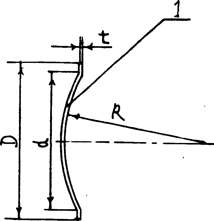
[0023] exist figure 1 Among them, the structure of the spherical microchannel plate 1 is exactly the same as that of the planar microchannel plate 1, but the shape is different. The thickness t of the spherical micro-channel plate 1 in this embodiment is 1.0 mm, and the shape of the spherical micro-channel plate 1 is that the middle part is a spherical crown, and the outer edge of the spherical crown is connected with a ring as a whole. The outer diameter D of the spherical microchannel plate 1 is 65 mm, the bottom surface diameter d of the spherical crown is 55 mm, the spherical radius R is 165 mm, R / d is 3, and the diameter of each microchannel is 10 μm.
[0024] Its preparation method is as follows:
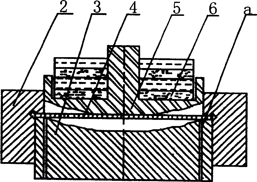
[0025] 1. Prepare the planar micro-channel plate according to the conventional method 4
[0026] Prepare the flat micro-channel plate 4 according to the conventional method, that is, put the core material of the solid mandrel into the hollow glass tube, put it into the heati...
Embodiment 2
[0034] In the present embodiment, the thickness t of the spherical microchannel plate 1 is 0.6 mm, the external diameter D of the spherical microchannel plate 1 is 35 mm, the bottom surface diameter d of the spherical cap is 25 mm, the spherical radius R is 20 mm, and R / d is 0.8, and the diameter of each microchannel is 10 μm.
[0035] In the preparation process, in the process step of fixing the planar microchannel plate 4 on the mould, the pressure generated by placing the counterweight 6 on the upper mould 5 is 10g / cm 2 , in the process step of making the protected area, it is reduced in a hydrogen furnace at 300°C for 6 hours. Other processing steps are identical with embodiment 1.
Embodiment 3
[0037] In the present embodiment, the thickness t of the spherical microchannel plate 1 is 1.5 mm, the external diameter D of the spherical microchannel plate 1 is 100 mm, the bottom surface diameter d of the spherical cap is 90 mm, the spherical radius R is 450 mm, and R / d is 5.0, and the diameter of each microchannel is 10 μm.
[0038] In the process step of fixing the planar microchannel plate 4 on the mould, the pressure generated by placing the counterweight 6 on the upper mould 5 is 20g / cm in the preparation process. 2 , in the process step of making the protected area, it is reduced in a hydrogen furnace at 350°C for 4 hours. Other processing steps are identical with embodiment 1.
PUM
| Property | Measurement | Unit |
|---|---|---|
| Thickness | aaaaa | aaaaa |
| Bottom diameter | aaaaa | aaaaa |
| Thickness | aaaaa | aaaaa |
Abstract
Description
Claims
Application Information
 - R&D
- Intellectual Property
- Life Sciences
- Materials
- Tech Scout
- Unparalleled Data Quality
- Higher Quality Content
- 60% Fewer Hallucinations
Browse by: Latest US Patents, China's latest patents, Technical Efficacy Thesaurus, Application Domain, Technology Topic, Popular Technical Reports.
© 2025 PatSnap. All rights reserved.Legal|Privacy policy|Modern Slavery Act Transparency Statement|Sitemap|About US| Contact US: help@patsnap.com


