
Differential protection device with simplified protection parameter adjustment means

A differential protection device, technology of protection device, applied in the direction of automatic disconnection emergency protection device, emergency protection circuit device, calibration/search protection device, etc., can solve the problems of unreliability, high cost, and complicated implementation.

Active Publication Date: 2005-07-27
SCHNEIDER ELECTRIC IND SAS
View PDF0 Cites 9 Cited by
  • Summary
  • Abstract
  • Description
  • Claims
  • Application Information

AI Technical Summary

Problems solved by technology

Implementation of this type of specific selector switch is complex, costly and unreliable
The volume occupied by this selector switch is relatively large

Method used


Image

  • Differential protection device with simplified protection parameter adjustment means
  • Differential protection device with simplified protection parameter adjustment means
  • Differential protection device with simplified protection parameter adjustment means

Examples


Embodiment Construction

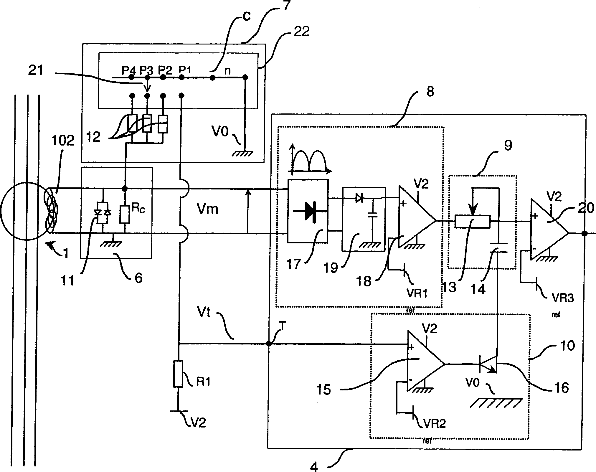
[0027] The protection device includes at least two protection parameter adjustment components. These protection parameters mainly relate to the fault current threshold and the time delay, ie the time during which the fault current can flow.

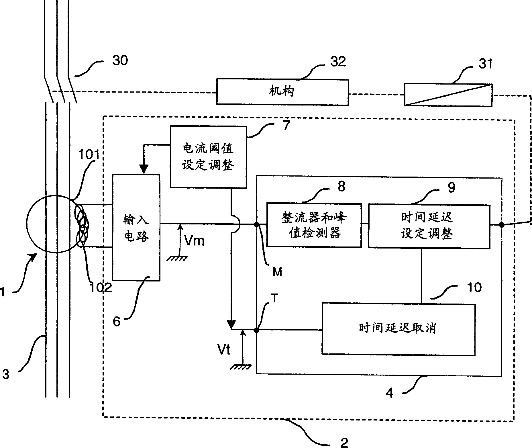
[0028] According to an embodiment of the present invention, figure 2 A protection device comprising a current sensor 1 , a trip circuit 4 , a component 7 for adjusting a fault current threshold setting and a component 9 for adjusting a time delay setting is shown in the form of a block diagram.

[0029] The current sensor 1 comprises a measuring toroid with a magnetic circuit 101 arranged around the conductor to be protected, the current wire 3 . The current wire 3 thus forms the primary winding of the measuring magnetic ring. The secondary winding 102 is connected to the input circuit 6 of the processing unit 2 . Secondary winding 102 provides circuit 6 with a signal representative of the differential current capable of flowing in cu...


PUM


Abstract

A differential protection device comprises differential current measuring means and a processing unit which comprises means for adjusting the fault current threshold setting and means for adjusting a time delay, and which is connected to said measuring means to receive a signal representative of a differential current. The means for adjusting the fault current threshold setting comprise switching means having a contact able to take at least two positions to select a fault current threshold for each of the positions, and to select for at least one of said positions a minimum or reduced time delay value whatever the initial setting of the time delay setting means.

Description

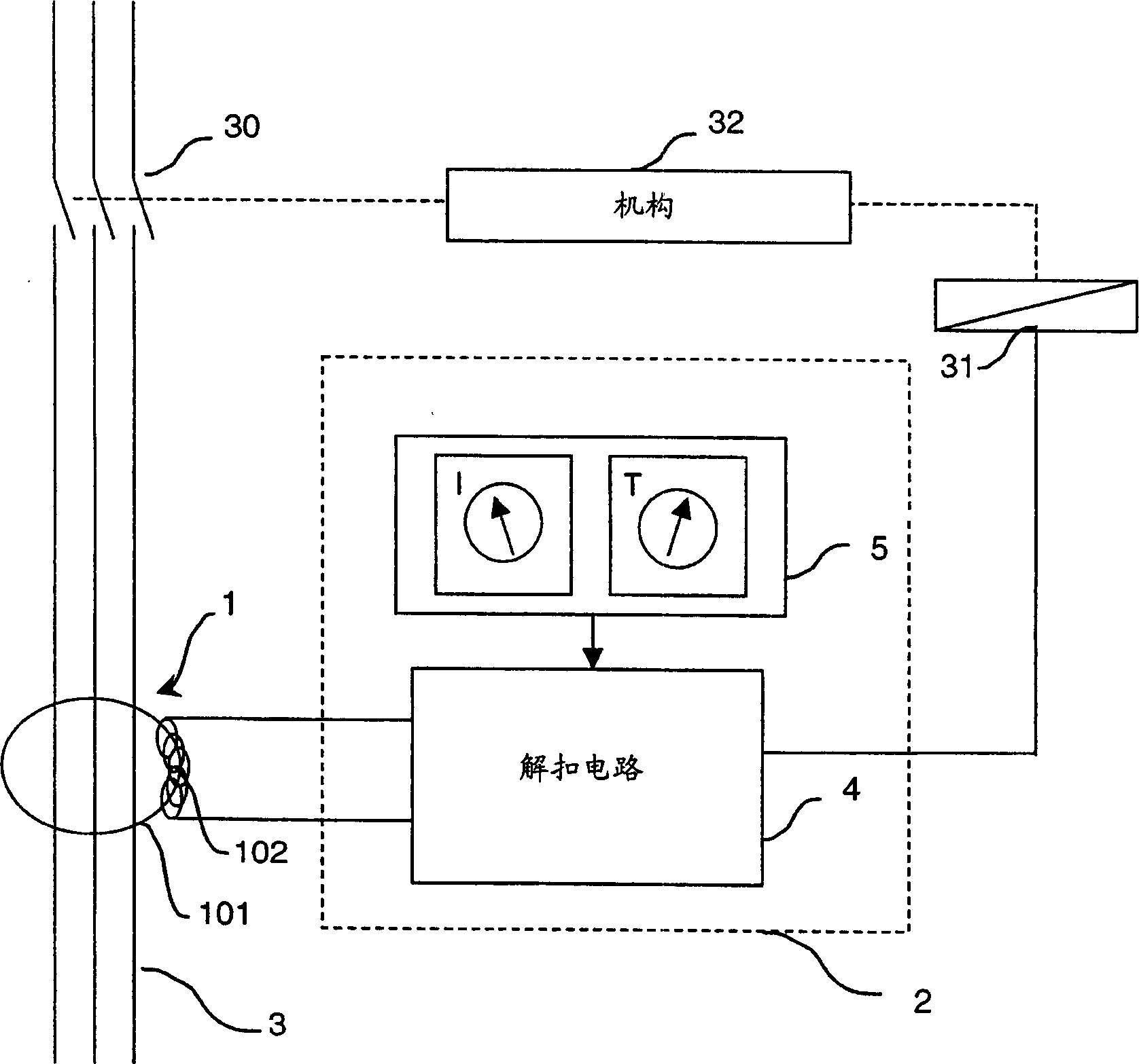
technical field [0001] The invention relates to a differential protection device comprising: [0002] differential current measurement components, and [0003] A processing unit, including means for adjusting the fault current threshold setting and means for adjusting the time delay setting, is connected to the measurement means for receiving a signal representative of the differential current. [0004] The invention also relates to a circuit breaker comprising said differential protection device. Background technique [0005] Such as figure 1 As shown, in a known manner, the differential protection device comprises a current measuring assembly 1 connected to a processing unit 2 . The measuring component is generally a current sensor, which provides a signal representation of the differential current capable of flowing in the current line 3 . [0006] This type of differential protection is generally associated with a breaking mechanism 32 of contacts 30 placed in series...

Claims


Application Information

Patent Timeline
Patent Type & Authority Applications(China)
IPC IPC(8): H01H83/14H01H69/01H01H83/02H02H3/00H02H3/093H02H3/33
CPCH02H3/33H02H3/093H02H3/006
Inventor 多米尼克·博多德
Owner SCHNEIDER ELECTRIC IND SAS
Learn More