
Optical data storage medium and use of such medium

A storage medium, optical data technology, applied in data recording, information storage, optical record carrier, etc.

Inactive Publication Date: 2005-07-27
KONINKLIJKE PHILIPS ELECTRONICS NV
View PDF0 Cites 0 Cited by
  • Summary
  • Abstract
  • Description
  • Claims
  • Application Information

AI Technical Summary

Problems solved by technology

Currently, there is little tendency to consider switchable layers such as thermochromic, photochromic or electrochromic layers

Method used


Image

  • Optical data storage medium and use of such medium
  • Optical data storage medium and use of such medium
  • Optical data storage medium and use of such medium

Examples


Embodiment Construction

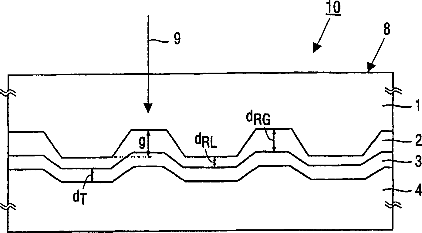
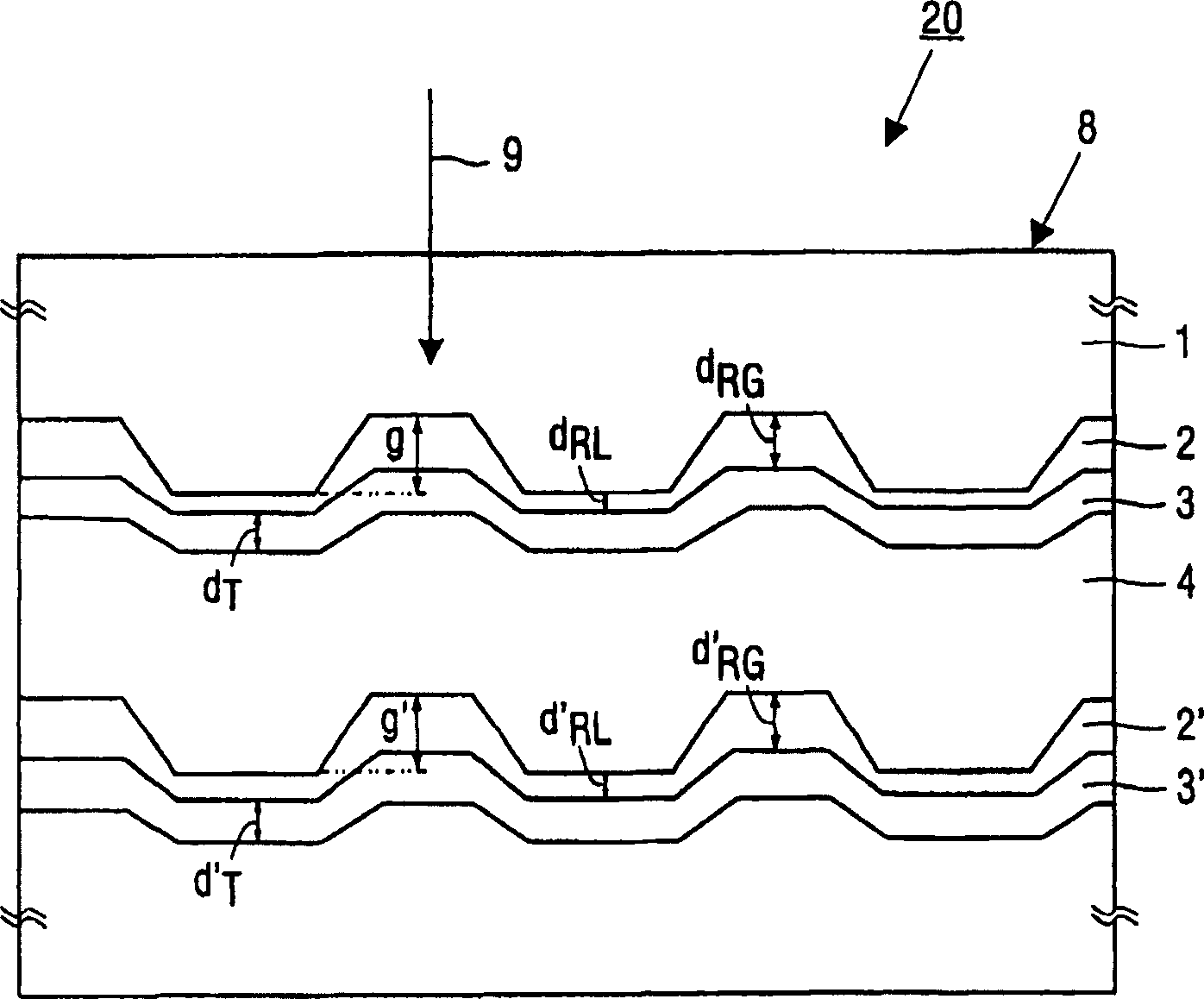
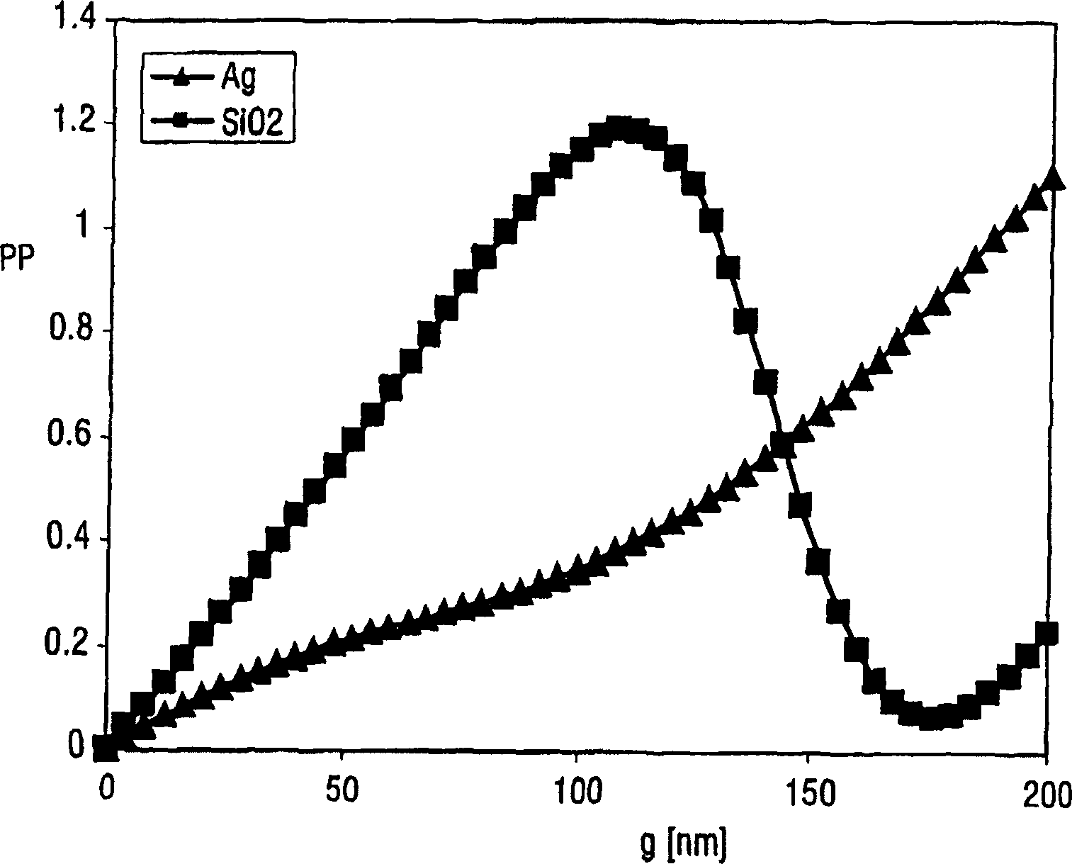
[0038] figure 1 A schematic cross-sectional view of an optical data storage medium 10 according to the invention for recording by means of a focused beam 9 is shown in . The beam is a laser beam with a wavelength [lambda] of approximately 655 nm and which penetrates the entrance face 8 of the medium during recording. The numerical aperture (NA) of the focused beam is 0.65. The medium comprises a base 1 comprising guide grooves of depth g. The guide groove is located on the side of the substrate opposite to the incident surface 8 . The recording stack 2 , 3 in layers is located on the substrate 1 on the side of the guide groove. The recording stack comprises a write-once recording layer 2, given by the complex refractive index at said wavelength n ~ R = 2.45 - i * 0.08 Composed of azo dyes, the thickness of the groove part is d RG =80nm, t...


PUM

PropertyMeasurementUnit
thicknessaaaaaaaaaa
thicknessaaaaaaaaaa
thicknessaaaaaaaaaa

Abstract

An optical data storage medium (10) for recording by means of a focused radiation beam (9) having a wavelength lambd is described. The beam enters through an entrance face (8) of the medium during recording. The medium at least comprises a substrate (1), including a guide groove with a depth g. The guide groove is present at the side of the substrate opposite to the entrance face. A recording stack (2, 3) of layers is present adjacent the substrate (1) at the side of the guide groove. The stack includes a write once recording layer (2) of a material having a complex refractive index R = nR - i*kR at the wavelength lambd and having a thickness d(RG) in the groove portion and a thickness d(RL) in the portion between grooves. A non-metallic layer (3) of a substantially transparent material, is present adjacent the write-once recording layer (2). The groove depth g is in the range (lambd / 655)*20 nm < g < (lambd / 655)*140 nm with lambd expressed in nm. This range achieves a sufficient push-pull tracking signal and a sufficient modulation of recorded marks.

Description

technical field [0001] The invention relates to an optical data storage medium for recording by means of a focused beam of wavelength λ which penetrates the entrance surface of the medium during the recording process, the medium comprising at least: [0002] a substrate comprising a channel of depth g present on the side of the substrate opposite the incident face, [0003] A recording stack on the side of said guide groove on a substrate, the stack comprising: [0004] The write-once recording layer has a complex refractive index when the wavelength is λ n ~ R = n R - i * k R Composed of materials, the thickness of the groove part is d RG , the thickness of the part between grooves is d RL , the recording layer is adjacent to the substrate, [0005...

Claims


Application Information

Patent Timeline
Patent Type & Authority Applications(China)
IPC IPC(8): G11B7/007G11B7/09G11B7/24035G11B7/2405G11B7/24062G11B7/24076G11B7/24079G11B7/24085G11B7/258
CPCG11B7/007G11B7/0938G11B7/24G11B7/24038G11B7/246
Inventor H·C·F·马坦施
Owner KONINKLIJKE PHILIPS ELECTRONICS NV
Learn More