Microstrip antenna for an identification appliance

A technology for identifying devices and microstrip antennas, which is applied to antennas, antennas, and antenna equipment with additional functions suitable for movable objects, and can solve problems such as antenna detuning, antenna circuit impedance mismatch, and distortion

Inactive Publication Date: 2005-07-27
PRECISION DYNAMICS CORPORATION
View PDF9 Cites 8 Cited by
  • Summary
  • Abstract
  • Description
  • Claims
  • Application Information

AI Technical Summary

Problems solved by technology

However, when on or near the surface of the body, the reactive near-field (the electric and magnetic fields closest to the antenna) is distorted by body tissue, causing an impedance mismatch between the antenna and the circuitry directly connected to it
This mismatch actually detunes the antenna and reduces the amount of EM energy radiated away from the body

Method used


Image

  • Microstrip antenna for an identification appliance
  • Microstrip antenna for an identification appliance
  • Microstrip antenna for an identification appliance

Examples


Embodiment Construction

[0023] For use in this specification, the meaning of "in (in)", whether used alone or in a compound word such as "therein", includes "in (in)" and "on (on)"; "radio frequency identification" and "RFID" refer to identification by radio frequency communication.

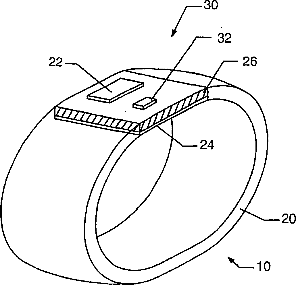
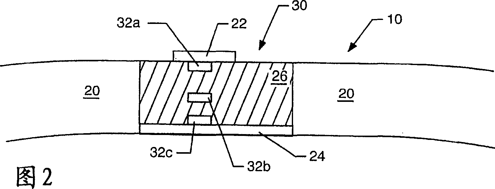
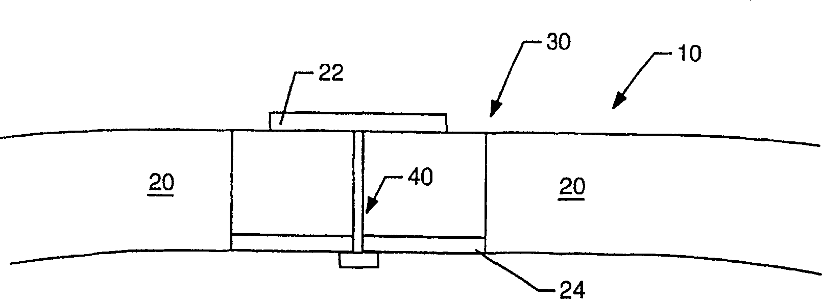
[0024] figure 1 An example embodiment of an identification device 10 comprising a microstrip antenna 30 as part thereof is shown. The microstrip antenna 30 is preferably a patch antenna. The identification device 10 has a structure 20 supporting a communication circuit 32 such as an RFID circuit. Communications circuitry 32 may be adapted to communicate with any type of system, network or device, and may use any communication protocol, including Bluetooth or IEEE 802.11. For more information about the Bluetooth protocol, please visit the website http: / / www.bluetooth.com . In this strap embodiment, identification device 10 includes a structure 20 adapted to be worn, strapped or carried by a person. The identificat...


PUM


Abstract

An identification appliance, such as a wristband, bracelet, patch, headband, necklace, card, sticker, or other wearable appliance, has an improved patch or microstrip antenna. The microstrip antenna comprises a conductive patch layer, a conductive ground layer and a dielectric layer in between the conductive layers. The microstrip antenna is mounted to or disposed in the identification appliance, where preferably the ground layer is closest to the user and the patch layer is furthest from the user. Electronic circuits may be located in the dielectric layer, on a surface of a conductive layer, or on another part of the identification appliance. Connecting holes through the dielectric layer may allow circuits to be connected to a conductive layer or layers. This improved antenna resolves detuning and communication degradation problems.

Description

technical field [0001] The field of the invention relates generally to antennas for identification devices such as wristbands, and more particularly to microstrip antennas or patch antennas for identification devices such as wristbands. Background technique [0002] The disclosure concerns an improved identification wristband, bracelet, armband, headband, necklace, card, sticker or other wearable article, collectively referred to as "strap" or "identification device" for convenience. Identification tapes have become a convenient and effective way of identifying people without permanently marking them. A fundamental advantage of the strap is that it is eventually removable. Identification straps typically include a flexible wrist strap that is longer than it is wide and a closure or guard for attaching and keeping the strap securely around the wearer's wrist. A portion of the strap may be used to imprint or otherwise affix identification or other information about the weare...

Claims


Application Information

Patent Timeline
Patent Type & Authority Applications(China)
IPC IPC(8): G06K19/077G06K19/07H01Q1/22H01Q1/27H01Q1/38H01Q1/44H01Q9/04H04B5/02
CPCH01Q9/0407H01Q1/273G06K19/07762H01Q1/22H01Q1/2225H01Q9/0471H01Q1/38
Inventor 迈克尔·L.·拜格尔
Owner PRECISION DYNAMICS CORPORATION
Why Eureka
Try Eureka