
Electric wave correction clock

A technology for clocks and radio waves, applied in the field of radio wave correction clocks, can solve the problem that the user cannot see the time display of the display unit, and achieve the effects of reducing the influence of noise, improving the receiving sensitivity and improving the convenience.

Inactive Publication Date: 2005-08-03
RHYTHM CO LTD
View PDF2 Cites 2 Cited by
  • Summary
  • Abstract
  • Description
  • Claims
  • Application Information

AI Technical Summary

Problems solved by technology

In order to eliminate this influence, when receiving the standard time signal, although it is also considered to stop the driving signal so that the display unit does not display the time, there is a problem that if all the display items are simply not illuminated, for example, the user cannot see the time. Time display of the display unit

Method used


Image

  • Electric wave correction clock
  • Electric wave correction clock
  • Electric wave correction clock

Examples


Embodiment Construction

[0060] Embodiments of the present invention will be described below with reference to the drawings.

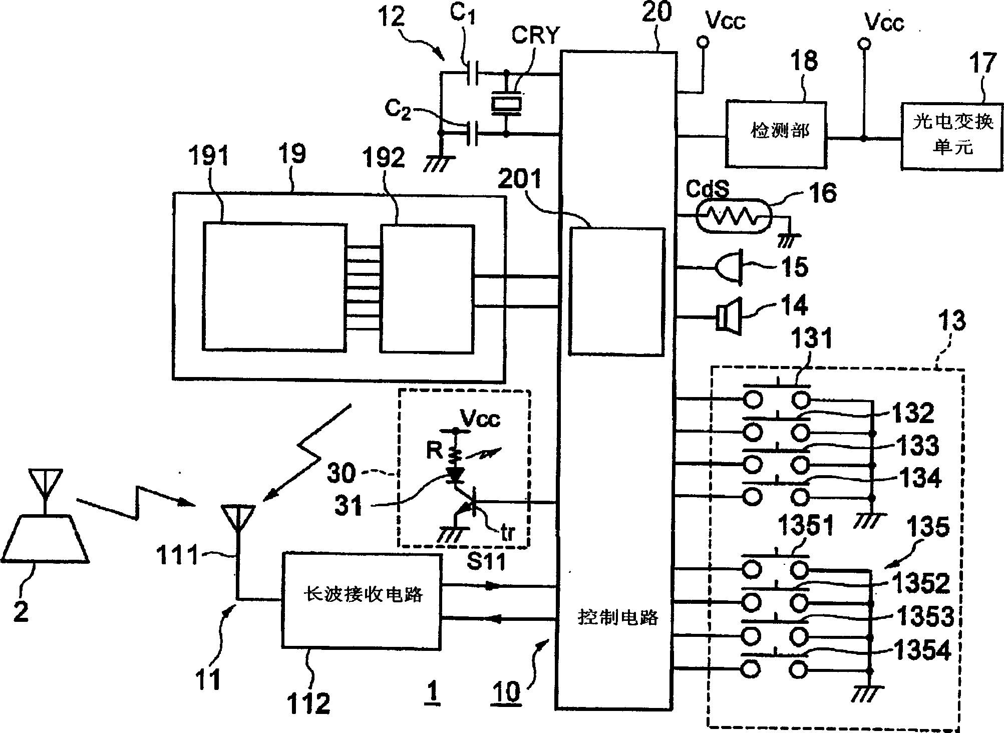
[0061] figure 1 Shown is a block diagram of an embodiment of a signal processing system of a radio-controlled timepiece according to the present invention.

[0062] The radio-controlled timepiece 1 according to this embodiment receives a standard radio signal including a standard time signal transmitted from a standard radio transmission station 2, and corrects the internally kept time based on the reception result.

[0063] The signal processing system circuit 10 of the radio-controlled timepiece 1 related to this embodiment, such as figure 1 As shown, it has a standard radio wave signal receiving system 11 as a receiving device, an oscillating circuit 12, a switch group 13, a speaker 14, a microphone 15, a light sensor 16 as a light and dark detection device, a conversion unit 17, a detection unit 18, and a display device. A display unit 19 , a control circuit 20 as a cont...


PUM


Abstract

The invention provided a radio-controlled watch that can improve the success rate in reception, while providing a predetermined display and capable of comfortable use, without loss in the user convenience. There is provided a control circuit 20 that sets the number of receipt n; decides whether the reception is successful for each reception; makes another reception, when reception is unsuccessful; and then supplies a display control signal to a display part 19, such that suppresses the generation of drive signals so as to increase display items to be switched the lights off from among a plurality of display items responding to the number of receipt increasing. Thus, the display action of the display part 19 which is a noise-generating source can be changed in matching with the receiving condition.

Description

technical field [0001] The present invention relates to, for example, a radio-controlled timepiece that performs time correction after receiving a radio signal including a standard time signal. Background technique [0002] There is known a timepiece having a display device such as a liquid crystal display device (also called an LCD (Liquid crystal display, liquid crystal display) panel) that displays the time measured by an internal timekeeping unit (hereinafter referred to as an internal clock). [0003] In the timepiece described above, for example, time data corresponding to the time kept by the internal timepiece is input to the drive circuit of the display unit. The drive circuit outputs a drive signal corresponding to the input time data to the LCD panel. The LCD panel displays the time according to the drive signal. [0004] Also known is a radio-controlled timepiece that has a display device such as an LCD panel, receives a standard radio signal including a standa...

Claims


Application Information

Patent Timeline
IPC IPC(8): G04C9/00G04G5/00G04G9/00G04R20/00G04R20/08
Inventor 田边彻福田正雄
Owner RHYTHM CO LTD
Learn More