Turbo charger with means on the shaft for axially securing of said shaft if the compressor wheel bursts

一种涡轮增压器、压缩机转子的技术,应用在用于弹性流体的泵送装置的部件、燃气轮机装置、安全装置等方向,能够解决脱落、费时、加固昂贵等问题,达到防止影响、使用简单、价格低廉的效果

Inactive Publication Date: 2005-08-03
ABB (SCHWEIZ) AG
View PDF0 Cites 10 Cited by
  • Summary
  • Abstract
  • Description
  • Claims
  • Application Information

AI Technical Summary

Problems solved by technology

However this reinforcement is quite expensive and time consuming, and in the case of high axial forces acting on the shaft generated by the turbine, the shaft can still fall out of the housing and cause serious accidents

Method used


Image

  • Turbo charger with means on the shaft for axially securing of said shaft if the compressor wheel bursts
  • Turbo charger with means on the shaft for axially securing of said shaft if the compressor wheel bursts
  • Turbo charger with means on the shaft for axially securing of said shaft if the compressor wheel bursts

Examples


Embodiment Construction

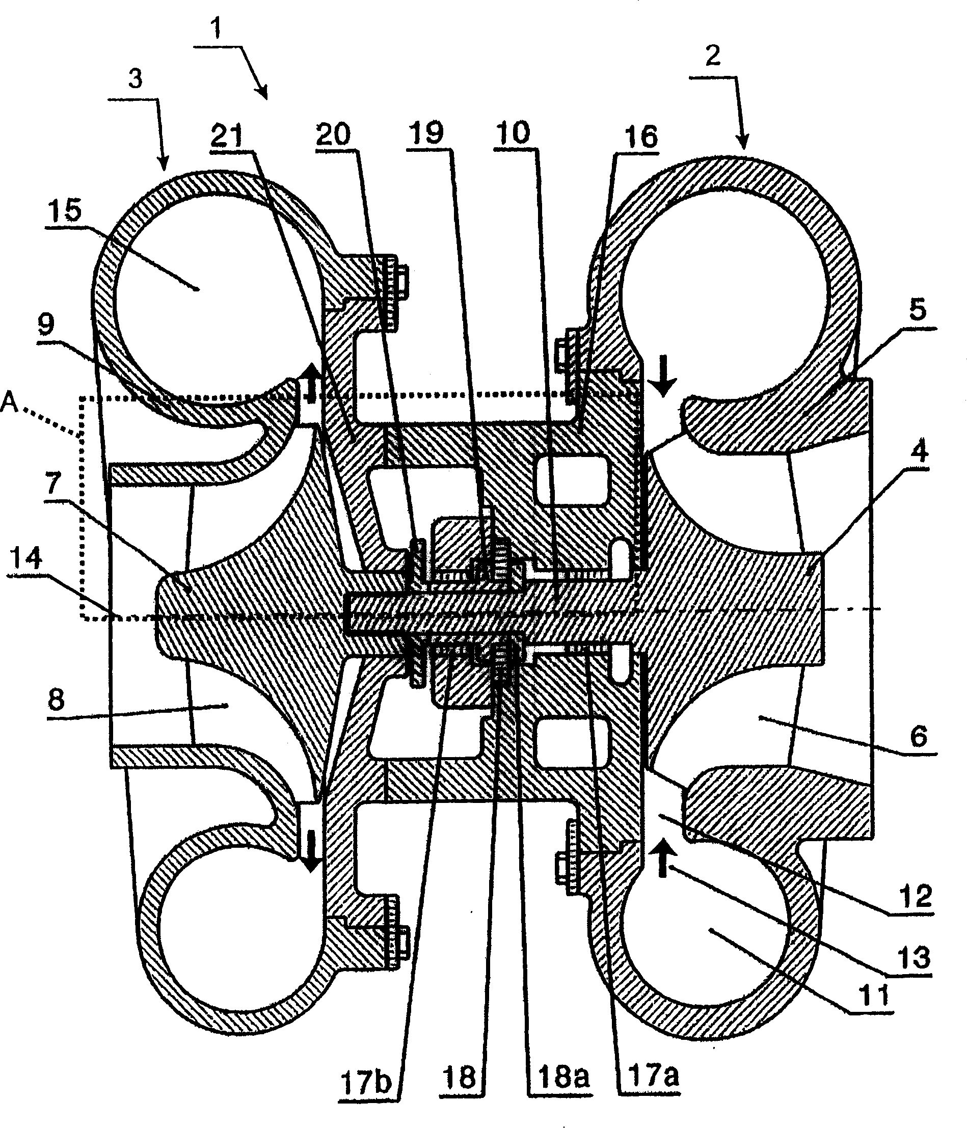
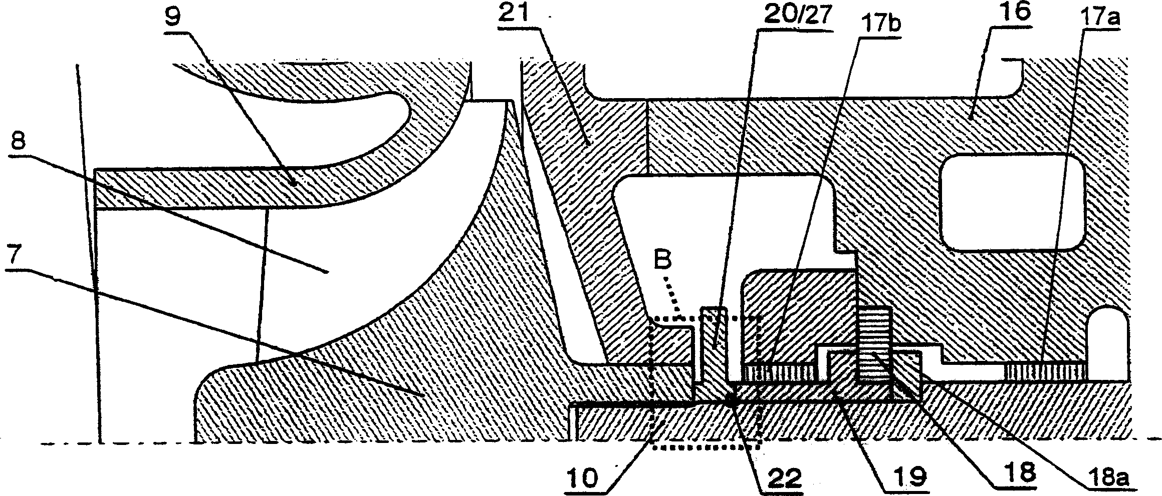
[0015] figure 1 A turbocharger 1 is shown schematically in longitudinal section, comprising a turbine 2 and a compressor 3 . The turbine 2 essentially comprises a turbine 4 with turbine blades 6 and a turbine housing 5 surrounding the turbine 4 . The compressor 3 comprises a compressor rotor 7 with compressor blades 8 and a compressor housing 9 surrounding the compressor rotor 7 . The turbine wheel 4 and the compressor rotor 7 are connected to one another via a shaft 10 , which is supported in a bearing housing by means of various bearing elements. In the exemplary embodiment shown here, the turbine 2 and the compressor 3 are designed as radial turbines and compressors. The turbine 4 is driven by the exhaust gases supplied to the turbine 4 via channels 11 , 12 in a known manner by an internal combustion engine (not shown). The exhaust gas decompressed and cooled by the decompression is discharged via an exhaust gas channel not further shown. Due to the rotational movement ...


PUM


Abstract

The device has a turbine with a turbine wheel and a compressor with a compressor wheel connected by shaft and in a housing so that an axial force acts on the turbine wheel and the connected shaft towards the turbine in the event of the compressor wheel bursting. An arrangement for axially securing the shaft and turbine wheel is arranged on the shaft to prevent axial shaft and turbine wheel motion towards the turbine if the compressor wheel bursts. The device has a turbine and a compressor connected to the turbine, whereby the turbine has a turbine wheel and the compressor contains a compressor wheel (7), which are connected together by a shaft (10) and are arranged in a housing (9,16) so that an axial force acts on the turbine wheel and the connected shaft towards the turbine in the event of the compressor wheel bursting. An arrangement (22) for axially securing the shaft and turbine wheel is arranged on the shaft to prevent axial movement of the shaft and turbine wheel towards the turbine if the compressor wheel bursts. AN Independent claim is also included for the following: an arrangement for axially securing a shaft and connected components.

Description

technical field Background technique [0001] The exhaust gas of the internal combustion engine can be used to compress the combustion air supplied to the internal combustion engine by means of a turbocharger. A turbocharger has for this purpose a turbine and a compressor that cooperate with a common shaft. The exhaust gases from the internal combustion engine are depressurized in the turbine and converted into rotational energy. The rotational energy obtained is transferred by means of this shaft to a compressor which compresses the air supplied to the internal combustion engine. The combustion process and energy yield of the internal combustion engine can be optimized by utilizing the energy of the exhaust gas for compressing the air that is fed to the combustion process within the internal combustion engine. [0002] Because on a turbocharger, usually the middle part of the casing needs to be pre-processed and closed due to the bearings contained inside, and may even be i...

Claims


Application Information

Patent Timeline
Patent Type & Authority Applications(China)
IPC IPC(8): F01D5/04F01D1/00F01D21/04F02B39/00F02B39/16F02C6/12
CPCF04D29/266F05D2220/40F02C6/12F01D21/045F01D21/04
Inventor A·科普M·加特曼T·格维亨博格
Owner ABB (SCHWEIZ) AG
Why Eureka
Try Eureka