Modeling method for residual oil catalytic cracking reaction mechanism model

A catalytic cracking and reaction mechanism technology, applied in catalytic cracking, cracking, petroleum industry and other directions, can solve the problems of not considering the composition and properties of raw materials, unreported application research, and limited application scope.

Inactive Publication Date: 2005-08-17
ZHEJIANG SUPCON SOFTWARE +1
View PDF2 Cites 14 Cited by
  • Summary
  • Abstract
  • Description
  • Claims
  • Application Information

AI Technical Summary

Problems solved by technology

The three-lumped model is simple and easy to use, but it does not consider the composition of raw materials, so its application range is greatly limited, and it is only used in some research and catalyst evaluation.
However, so far, the application research of the product distribution prediction model suitable for MIP process residual oil catalytic cracking unit has not been reported

Method used


Image

  • Modeling method for residual oil catalytic cracking reaction mechanism model
  • Modeling method for residual oil catalytic cracking reaction mechanism model
  • Modeling method for residual oil catalytic cracking reaction mechanism model

Examples


Embodiment Construction

[0078] Below in conjunction with accompanying drawing and by embodiment the present invention will be further described:

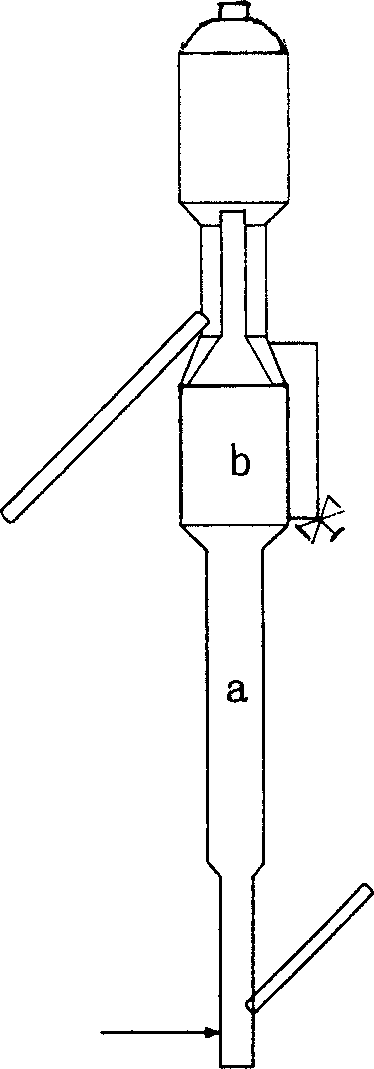
[0079] The validity of the model is verified by using the actual production historical data of a catalytic cracking unit for maximizing the production of isoparaffin residual oil in a certain petroleum refining company. The riser reactor is divided into two reaction zones a and b, such as figure 1 shown.

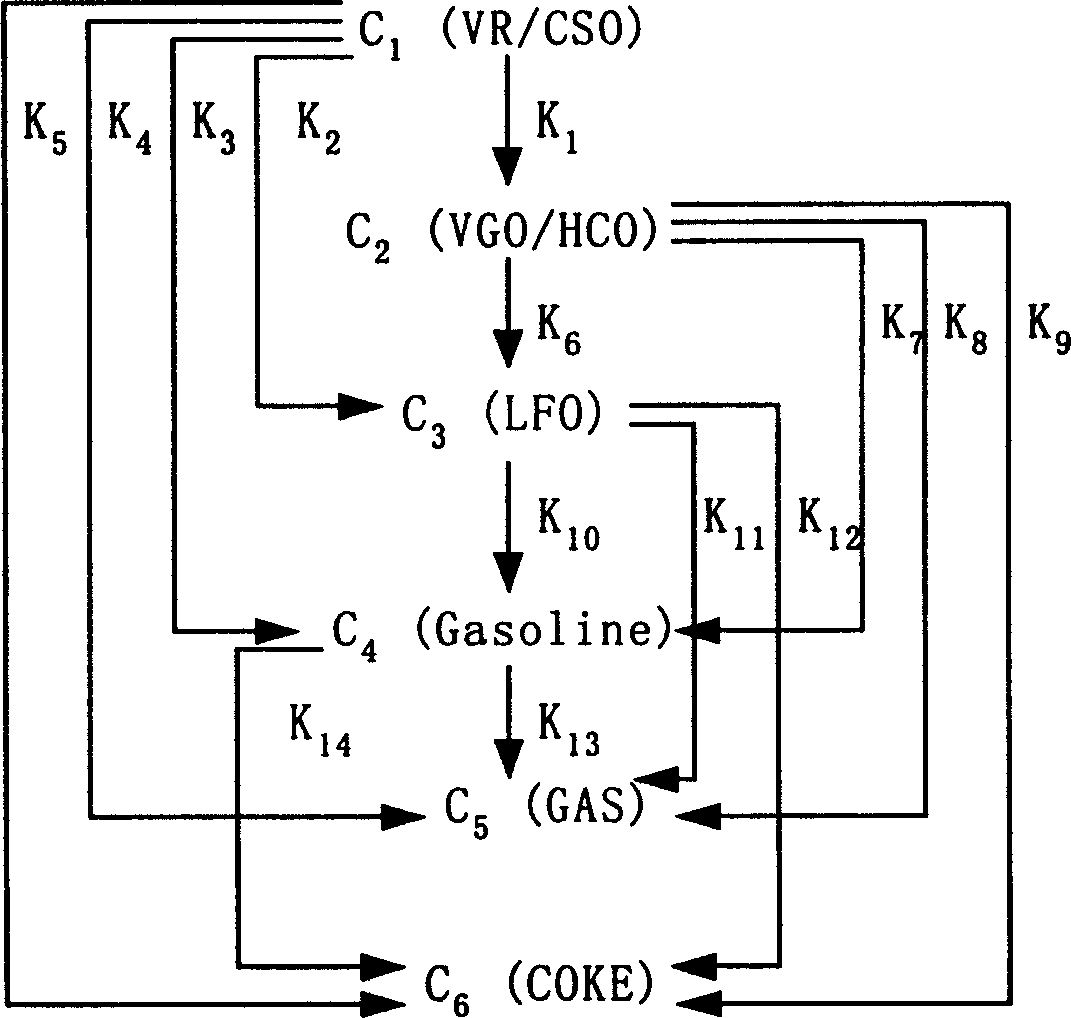
[0080] The reaction system is divided into residue-reducing slurry C according to the requirements of the present invention 1 (VR / CSO), wax oil back to refining oil C 2 (VGO / HCO), Diesel C 3 (LFO), petrol C 4 (Gasoline), liquefied gas dry gas C 5 (GAS) and coke C 6 (COKE) and other 6 aggregates, and establish a series-parallel reaction network for cracking reactions between each aggregate, and the rate constants of the chemical reactions in each step are marked on the graph, as shown in figure 2 shown.

[0081] According to the modeling method f...


PUM


Abstract

This invention discloses a model set up method for residual oil catalytic cracking reaction mechanism model, which divides the oil cut fraction into 6 lumps to set up serial and parallel reaction networks among 6 lumps and combines the character of the reactor with the experience dynamics equations among the lumps to set up a residual oil catalytic cracking reaction mechanism model. Besides, 6 device factors are set for calibrating the reacted dynamics rate constants among the lumps to increase the pretest accuracy of the model to product distribution.

Description

technical field [0001] The invention relates to a method for modeling the distribution prediction mechanism model of residual oil catalytic cracking products used for maximizing the production of isoparaffin catalytic cracking units. Background technique [0002] Catalytic cracking is one of the most important heavy oil lightening processes, and plays an important role in the production of light oil products such as gasoline and diesel. With the development of process technology, in order to obtain greater profits, people have carried out technological transformation on traditional catalytic cracking units, and continuously increased the amount of slag in the processed raw oil. At the same time, a large number of new residual oil catalytic cracking units have been put into operation . How to further improve the operation level of the residual oil catalytic cracking unit, and truly make the production unit run safely, stably, long, full, and optimally is one of the important...

Claims


Application Information

Patent Timeline
Patent Type & Authority Applications(China)
IPC IPC(8): C10G11/00
Inventor 王长明赵路军王建新古勇金晓明牟盛静
Owner ZHEJIANG SUPCON SOFTWARE
Why Eureka
Try Eureka