Supercharge Your Innovation With Domain-Expert AI Agents!

Dipolar permanent-magnet direct current motor

A DC motor and permanent magnet technology, applied in DC commutators, electrical components, electromechanical devices, etc., can solve problems such as backward structure, unreasonable design of magnetic circuit, and low efficiency of DC motor power conversion

Inactive Publication Date: 2005-08-17
王建功
View PDF0 Cites 1 Cited by
  • Summary
  • Abstract
  • Description
  • Claims
  • Application Information

AI Technical Summary

Problems solved by technology

[0002] The current DC motor has low power conversion efficiency, backward structure, and unreasonable magnetic circuit design

Method used


Image

  • Dipolar permanent-magnet direct current motor
  • Dipolar permanent-magnet direct current motor

Examples


Embodiment Construction

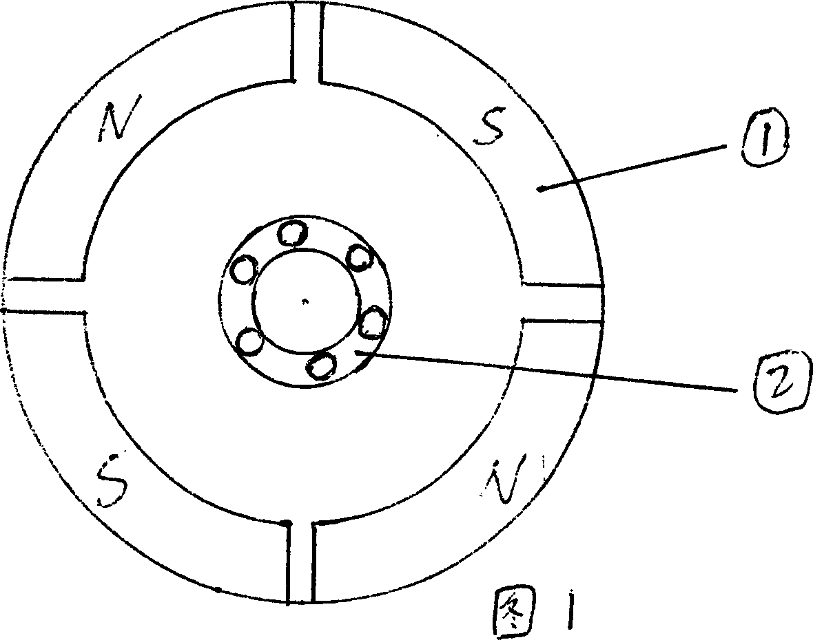
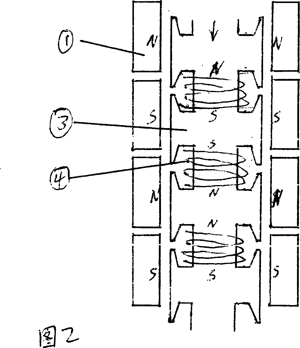
[0007] Figure 1 is a schematic plan view of the inner stator of the end cover; (1) represents the permanent magnet pole of the stator; (2) represents the bearing in the middle of the end cover. Figure 2 shows the schematic diagram of the rotor circumference surface development; (2) shows the stator permanent magnet pole; (3) shows the rotor core; (4) shows the coil.

[0008] To sum up, the present invention can use simple structural design, so that the product of the present invention can fully utilize permanent magnet energy and electric energy, greatly reduce cost, work stably and reliably, and be easy to use, and solve the problem of electric vehicle power, etc. The present invention is a novel, progressive and practical new design. The above descriptions are the specific embodiments of the present invention and the applied technical principles. If the equivalent changes are made according to the concept of the present invention, and the functions produced by it still do no...


PUM


Abstract

This invention relates to double-electrode permanent direct current motor, which comprises permanent magnetic materials, soft magnetic materials, and electron technique and mechanic process. The invention is aimed to develop permanent magnetic energy and fully uses electricity power and can be widely used in industry, agriculture, aviation, sailing, military, traffic, and study fields. Comparing with current motor, the invention adopt negative rotation as an ideal power.

Description

technical field [0001] The invention relates to a direct current motor, in particular to a bipolar permanent magnet direct current motor with reasonable structure and high efficiency. Background technique [0002] The existing DC motor has low power conversion efficiency, backward structure and unreasonable magnetic circuit design. In view of this, a structural form is provided, which can exploit the permanent magnet energy to the greatest extent, increase the utilization efficiency of electric energy, and solve the power of the electric vehicle. Exactly where the present invention's research and creation motivation lies. Aiming at the shortcomings of the prior art, the object of the present invention is to provide a DC motor, which realizes a low-cost and practical bipolar permanent magnet DC motor by using permanent magnetic materials, soft magnetic materials, electronic technology and mechanical manufacturing . Contents of the invention [0003] The stator of the pre...

Claims


Application Information

Patent Timeline
IPC IPC(8): H02K1/17H02K23/40
Inventor 王建功
Owner 王建功
Features
  • R&D
  • Intellectual Property
  • Life Sciences
  • Materials
  • Tech Scout
  • Unparalleled Data Quality
  • Higher Quality Content
  • 60% Fewer Hallucinations
Learn More