
Spindle motor
A motor and mandrel technology, applied in instruments, recording information storage, controlling mechanical energy, etc., can solve the problems of increased quantity, increased production cost, difficulty in different requirements, etc., to achieve the effect of reducing assembly steps, easy loading and unloading
- Summary
- Abstract
- Description
- Claims
- Application Information
AI Technical Summary
Problems solved by technology
Method used
Image

Examples
Embodiment Construction
[0021] Preferred embodiments of the present invention will be described with reference to the accompanying drawings.
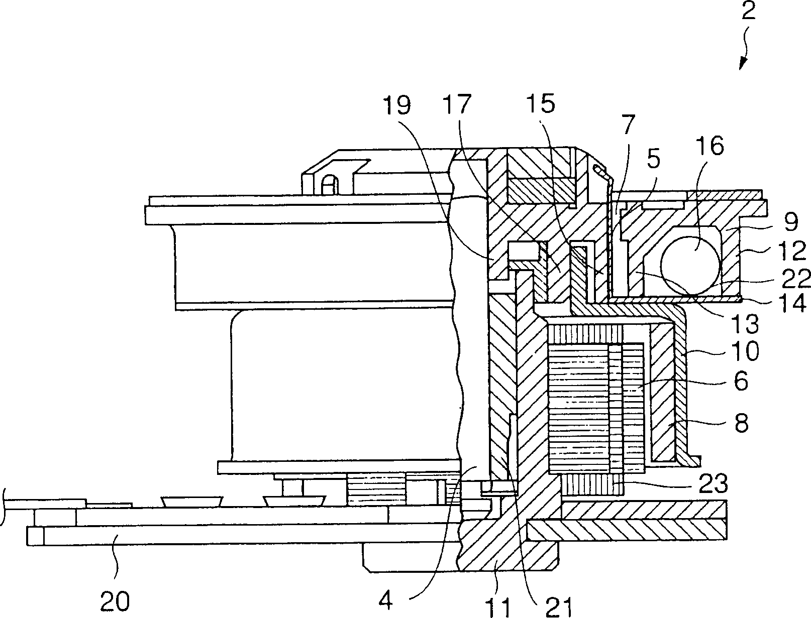
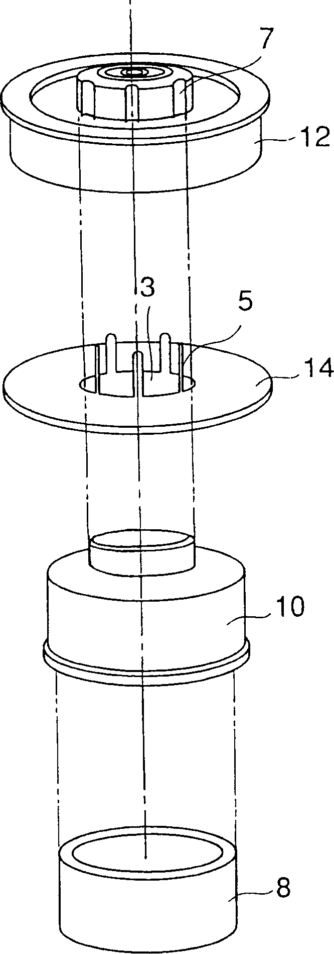
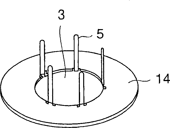
[0022] refer to figure 1 The spindle motor 2 of the embodiment of the present invention generally includes a motor assembly 31 composed of a rotating shaft 4, a stator 6, a rotor magnet 8, a rotor yoke 10 and a support 11, and also includes a turntable 12 and a bracket plate 14, and the core The shaft motor 2 is attached to the base plate 20 .
[0023] The rotor magnet 8 is a hollow cylindrical permanent magnet and is fixed to the inner circumference of the rotor yoke 10 which is fixedly connected to the rotary shaft 4 together with a turntable 12 .
[0024] The rotating shaft 4 is rotatably supported by a bearing 21 provided in a support 11 connected to the base plate 20 .
[0025] The stator 6 , which has a coil 23 wound therearound, is fixed to the support 11 and faces the inner circumferential surface of the rotor magnet 8 with a slight air gap between t...
PUM
| Property | Measurement | Unit |
|---|---|---|
| thickness | aaaaa | aaaaa |
Abstract
Description
Claims
Application Information