Printed circuit board structure for motor driving device

A printed circuit board and circuit board technology, which is applied in the structural connection of printed circuits, printed circuits connected with non-printed electrical components, printed circuits, etc., to achieve the effect of reducing the number of

Inactive Publication Date: 2005-08-31
FANUC LTD
View PDF1 Cites 4 Cited by
  • Summary
  • Abstract
  • Description
  • Claims
  • Application Information

AI Technical Summary

Problems solved by technology

[0007] In this conventional structure, by preparing multiple types of printed circuit boards with different circuit elements having the same conductive pattern, printed circuit boards can cope with different voltage specifications, but since the circuit components have limited allowable input voltage, so this structure is limited in its application to different specifications

Method used


Image

  • Printed circuit board structure for motor driving device
  • Printed circuit board structure for motor driving device
  • Printed circuit board structure for motor driving device

Examples


Embodiment Construction

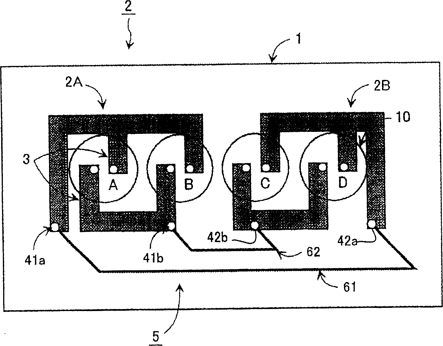
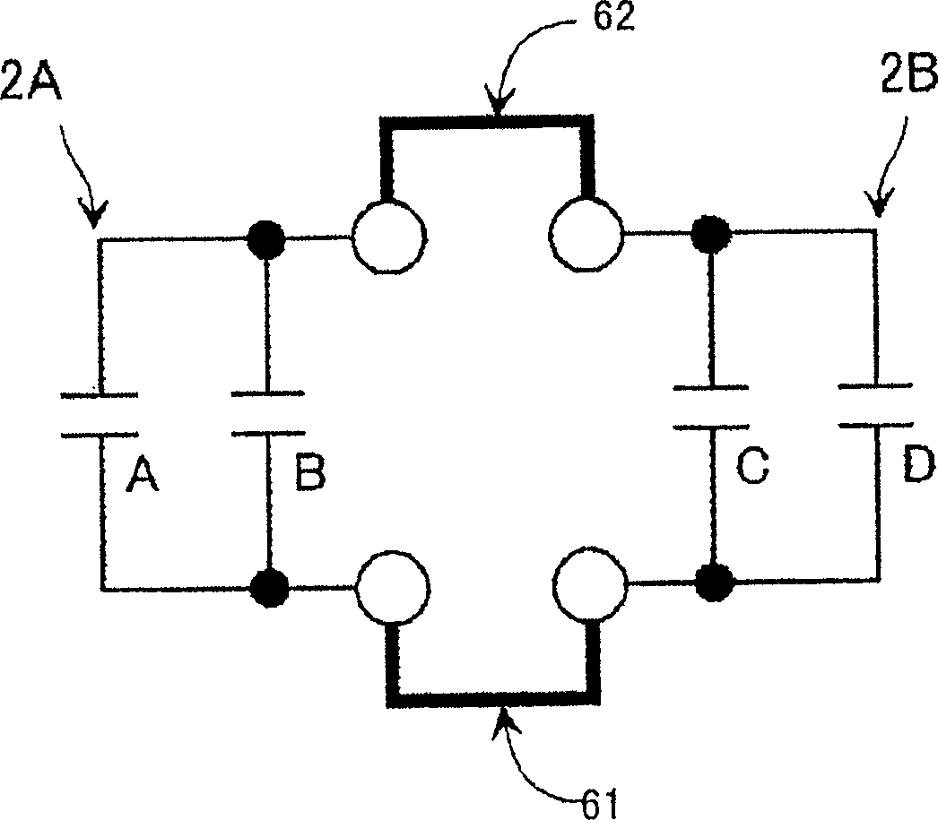
[0030] refer to Figure 1-4 A first embodiment of the present invention is described. Such as figure 1 As shown, the printed circuit board 2 of the first embodiment includes two conductive patterns 2A, 2B formed on the circuit board 1 and an optional connector 5 electrically connecting the conductive patterns 2A and 2B. In this embodiment, the optional connector 5 includes a shorting bar 6 .

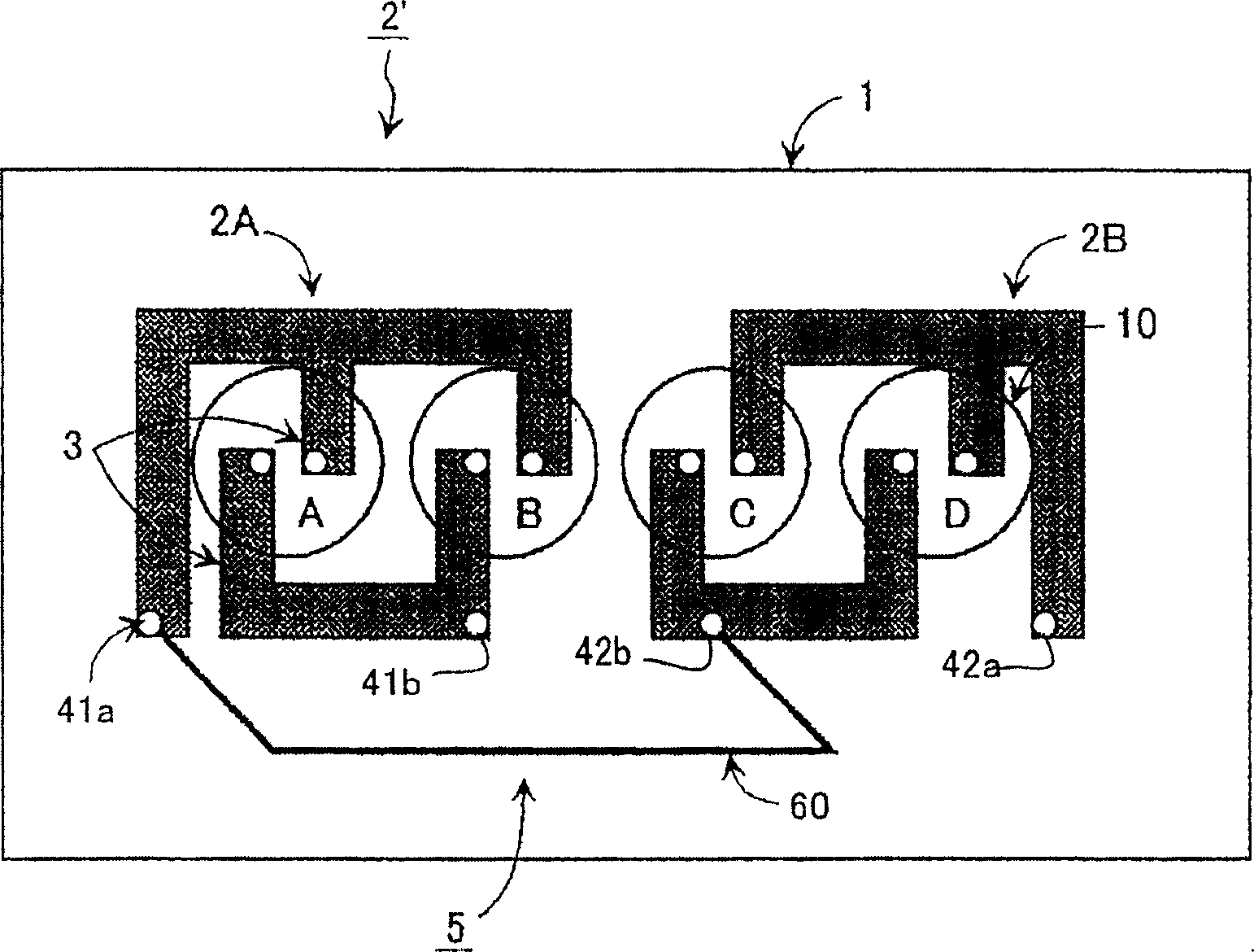
[0031] The two conductive patterns 2A and 2B formed on the circuit board 1 have substantially the same pattern, and each of the conductive patterns 2A and 2B has two pairs of electrodes 3 disposed oppositely. exist image 3 The printed circuit board 2' shown in has the same figure 1 The printed circuit board 2 shown in FIG. 2 has the same conductive patterns 2A and 2B, but they are connected differently by shorting bars and thus have a different capacitance than the printed circuit board 2 .

[0032] Two pairs of electrodes 3 provided in the conductive pattern 2A constitute a fi...


PUM


Abstract

A printed circuit board structure for a motor driving device in which the number of kinds of printed circuit boards for constituting inverter devices having different allowable input voltages are reduced. This printed circuit board structure comprises a plurality of conductive patterns and a selective connector. Each of the conductive patterns includes at least one pair of electrodes arranged in confronting relation to form a capacitor, and terminals electrically conducted with the electrodes. The selective connector selectively connects the terminals of the conductive patterns so that a capacitor circuit having predetermined capacitance is formed.

Description

technical field [0001] The present invention relates to a printed circuit board structure, and more particularly to a printed circuit board structure suitable for use in a commutator for driving an electric motor. Background technique [0002] The commutator device is widely used to drive induction motors because it efficiently drives general purpose induction motors at variable speeds. Combined with external cables, rated voltage and allowable input voltage, commutator devices have different specifications for different uses, and it is common practice to modify the entire construction or parts of the commutator to deal with specific uses. [0003] For example, in consideration of allowable input voltages of capacitors, a plurality of capacitors are used in parallel for low-voltage power supply specifications, while a combination of series connection and parallel connection of capacitors is used for high-voltage power supply specifications. [0004] Figure 12 Shown is a co...

Claims


Application Information

Patent Timeline
Patent Type & Authority Applications(China)
IPC IPC(8): H05K1/11H02M7/48H05K1/00H05K1/14H05K1/16
CPCH05K1/029H05K1/14H05K2203/171H05K1/162
Inventor 铃木直行稻叶树一
Owner FANUC LTD
Why Eureka
Try Eureka