Novel quick-speed elliptical polarized light measurement system

A technology of elliptically polarized light and measurement systems, applied in measurement devices, material analysis through optical means, instruments, etc., can solve problems such as application limitations and difficulties

Inactive Publication Date: 2005-09-07
FUDAN UNIV
View PDF0 Cites 30 Cited by
  • Summary
  • Abstract
  • Description
  • Claims
  • Application Information

AI Technical Summary

Problems solved by technology

However, since ordinary photometric ellipsometric systems use polarizer scanning to obtain ellipsometric parameters, although the test of ordinary optical parameters is fast enough, if it is applied to some

Method used


Image

  • Novel quick-speed elliptical polarized light measurement system
  • Novel quick-speed elliptical polarized light measurement system
  • Novel quick-speed elliptical polarized light measurement system

Examples


Embodiment Construction

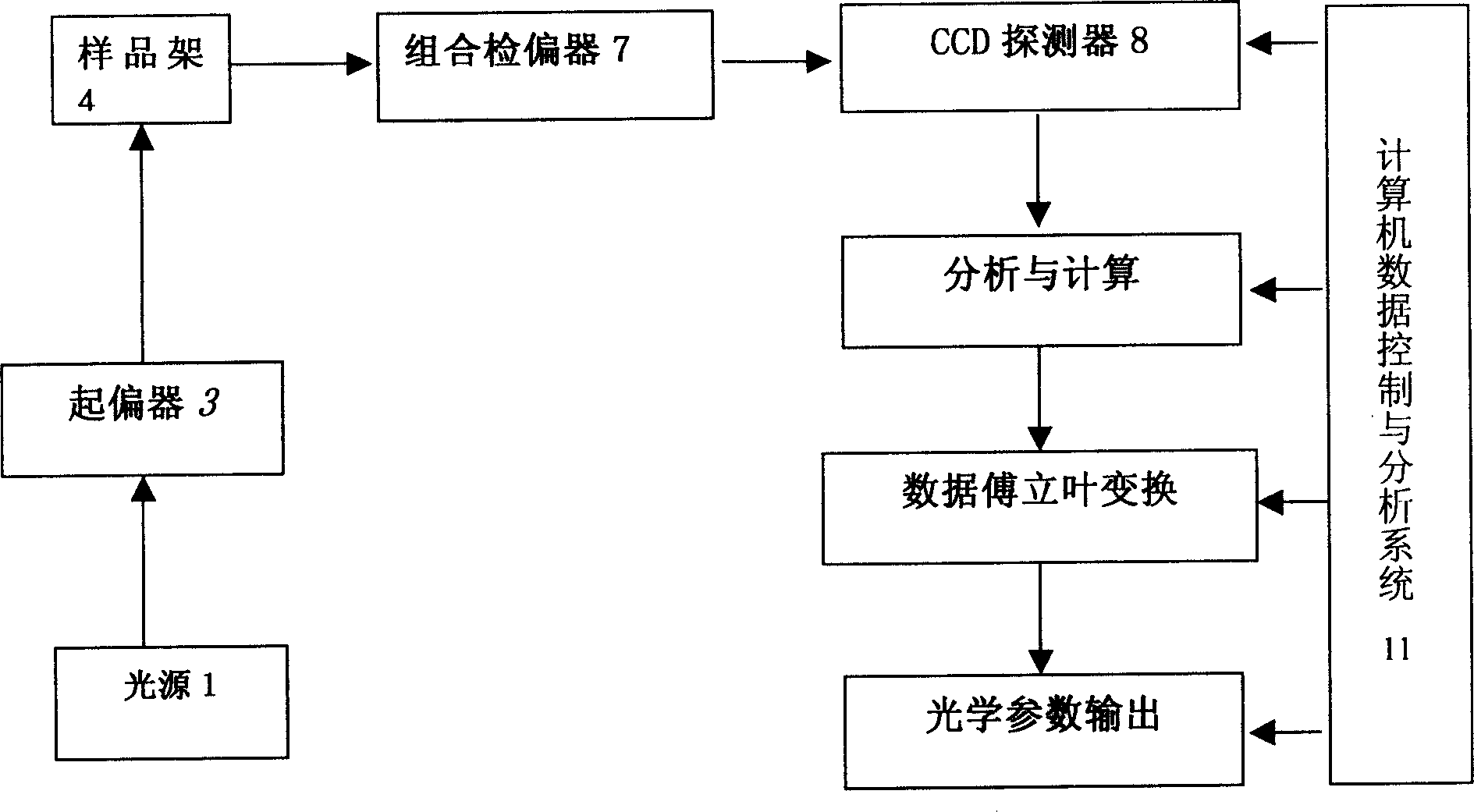
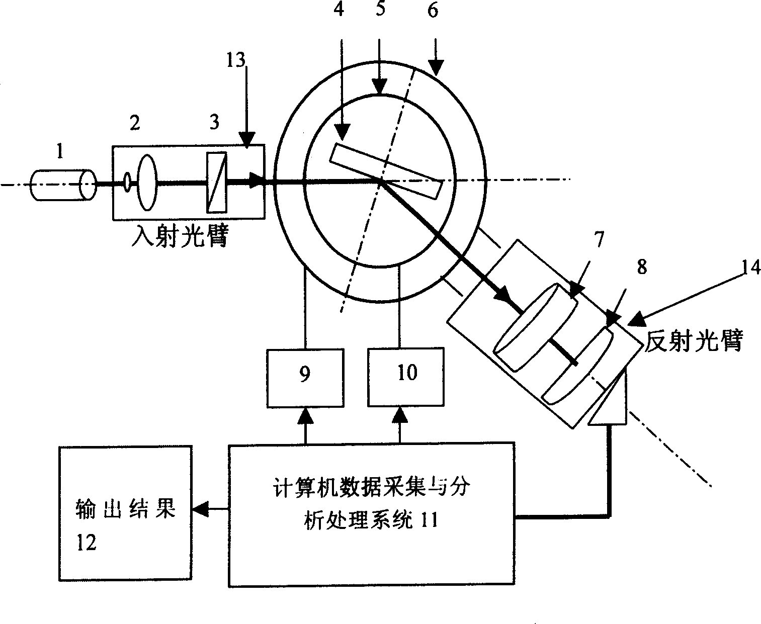
[0035] The novel fast ellipsometry system designed by the present invention has been used in Figure 1 , a special case is given here. In this example, the light source is a laser light source. After beam expansion, the light emitted by the laser light source is incident on the polarizer 3, and then incident on the sample, and is reflected by the sample to the combined analyzer 7, and the light emitted by the combined analyzer 7 is detected by the two-dimensional CCD respectively. Different areas of the area array detector 8 receive.

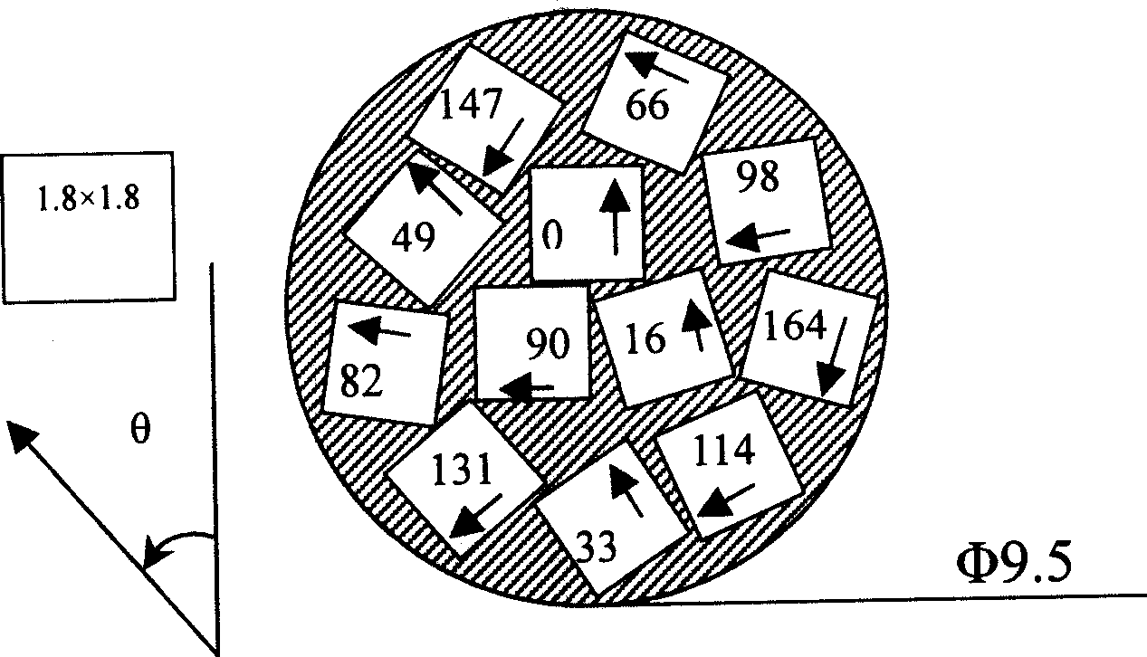
[0036] The combined analyzer 7 is composed of m miniature analyzers. m generally take 5-20. Azimuth angle θ of each sub-analyzer 1 , θ 2 ... θ m , roughly evenly distributed within 0-180°. The specific method of combining the polarizer is to process m (such as more than ten) small holes (such as square holes) in a hard material. The orientation of the square holes is different, and the direction angle is roughly uniform within the range of...


PUM


Abstract

The invention relates to a system for measuring elliptical polarised light quickly, which uses the combined analyzer and bidimensional CCD array detector to get the optical parameter of the material quickly, different from the traditional measuring system which uses mechanical rotation to control the analyzer or polarizer and scan the azimuth angle. So in the measuring process, the system cannot rotate any mechanical segment and increase the speed of measuring the optical parameter of every material violently.

Description

technical field [0001] The invention belongs to the technical field of optical and electronic devices, and in particular relates to a novel fast ellipsometric light measuring system. Background technique [0002] Ellipsometry is an optical measuring instrument, which is one of the most effective and reliable methods to obtain the optical properties, optical constants and film thickness of various information functional materials. For example, taking the high-performance Pentium chip manufacturing process as an example, in its complete process flow, it has to go through more than 40 ellipsometric detections. The development of optical communication technology depends on the research and development of a series of optical components such as high-performance optical waveguides, optical switches, optical amplifiers, and narrow-band filters. Fast, high-precision measurement and analysis of optical constants and optical properties. In addition, for some optical thin film devices,...

Claims


Application Information

Patent Timeline
IPC IPC(8): G01N21/17G01N21/21G06F19/00
Inventor 郑玉祥陈良尧张荣君李晶王松有杨月梅孙斌
Owner FUDAN UNIV
Why Eureka
Try Eureka