Data transfer memory

A data transmission and memory technology, applied in static memory, memory system, read-only memory, etc., can solve the problem of inability to reduce the number of components constituting a module, and achieve the effect of reducing the number of components

Inactive Publication Date: 2005-09-07
SANYO ELECTRIC CO LTD
View PDF0 Cites 8 Cited by
  • Summary
  • Abstract
  • Description
  • Claims
  • Application Information

AI Technical Summary

Problems solved by technology

[0016] However, in the above-mentioned prior art, because the data memory can only function as a slave device, so when the data stored in the data memory is to be transmitted to

Method used


Image

  • Data transfer memory
  • Data transfer memory
  • Data transfer memory

Examples


Embodiment Construction

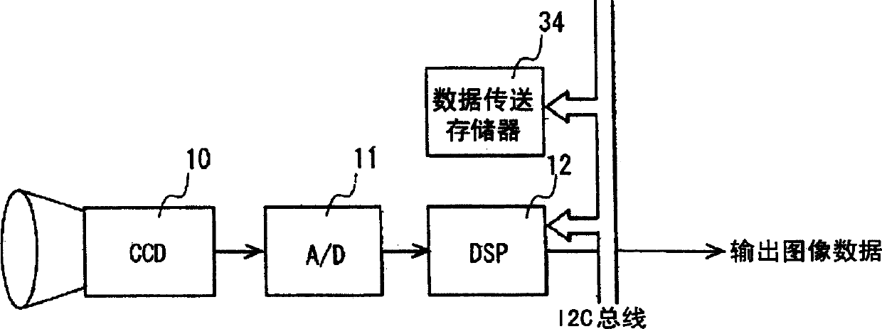
[0038] FIG. 1 is a block diagram showing the configuration of a module for a CCD camera according to an embodiment of the present invention. The camera module is composed of CCD10, A / D conversion circuit 11, and DSP12. These are the same as the conventional camera module shown in FIG. 11 . In this embodiment, the data transfer memory 34 is connected via an I2C bus. In the data transfer memory 34, a DSP control program and camera adjustment data (including, for example, white balance characteristics of the CCD 10, dispersion correction data of the mechanical shutter, etc.) and the like are stored.

[0039] The data transfer memory 34 acts as a master device when the power is turned on or the CCD10 is activated, and writes the DSP control program and camera adjustment data (such as white balance characteristics) into the slave device DSP12 through the I2C bus. Thereby, the DSP 12 becomes capable of performing predetermined image signal processing and camera adjustment (for exa...


PUM


Abstract

A data transfer memory for reducing the number of components in an electronic module. A master controller circuit provides a transfer start command to a master clock signal generator circuit when receiving an activation detection signal from a power activation detection circuit. As a result, the master clock signal generator circuit generates a basic clock signal, outputs the basic clock signal to an SCL line, and has a master transfer sequencer circuit execute a transfer sequence. The master transfer sequencer circuit transmits a start condition, data stored in the nonvolatile memory via a serial control circuit, and a stop condition to an SDA line synchronously with the basic clock signal.

Description

technical field [0001] The present invention relates to data transfer memory. Background technique [0002] The I2C bus is a 2-wire serial bus advocated by Philips. The I2C bus corresponds to the sending command of the master device, and the slave device acts. The operation of the I2C bus will be described using Figures 6 to 10. [0003] As shown in Fig. 6, when the SCL line is "H", the SDA line changes from "H" to "L", and becomes an active state. All actions start in the start state. When the SCL line is "H", the SDA line changes from "L" to "H", and becomes a stop state. Here, the SCL line is a serial clock line for inputting a serial clock, and the SDA line is a serial data line for data transfer. [0004] The sending command is carried out by changing the SDA line during the "H" period of the SCL line, and 8 bits are sent continuously. During the ninth clock cycle, the command-accepting slave device puts the SDA line to "L" and sends an acknowledgment of acceptanc...

Claims


Application Information

Patent Timeline
IPC IPC(8): G06F12/00G06F12/06G06F13/00G06F13/38H04N5/225
CPCG11C2216/30H04N5/376G11C16/26H04N25/74G06F13/00G06F13/16
Inventor 野田笃
Owner SANYO ELECTRIC CO LTD
Why Eureka
Try Eureka