Method for implementing power detection based automatic power control in optical network

An automatic power control and power detection technology, which is applied in the field of optical network communication, can solve the problems of complex multi-link cooperative work and the inability to realize full-automatic adjustment, and achieve strong anti-interference ability, good self-adaptive ability, and stable transmission performance Effect

Active Publication Date: 2005-09-07
HUAWEI TECH CO LTD
View PDF0 Cites 23 Cited by
  • Summary
  • Abstract
  • Description
  • Claims
  • Application Information

AI Technical Summary

Problems solved by technology

[0008] Similarly, the link power control method based on the wave number detection mechanism also showed some shortcomings in the actual application process. The shortcomings of this method mainly lie in the configuration cost and reliability of t

Method used


Image

  • Method for implementing power detection based automatic power control in optical network
  • Method for implementing power detection based automatic power control in optical network
  • Method for implementing power detection based automatic power control in optical network

Examples


Embodiment Construction

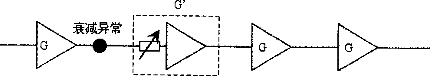
[0042] The method of the present invention realizes the low-cost full-automatic power control for the whole link through the detection means based on the power detection mechanism, and can effectively compensate the influence brought by the accumulated noise of the optical amplifier in the link.

[0043] The implementation method of automatic power control based on power detection in the optical network of the present invention mainly includes the following processing procedures:

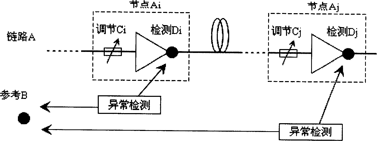
[0044] (1) Configure the power control link for the entire link, that is, configure the entire link as one or more independent power control links according to the actual business transmission conditions, and each power control link contains a or nodes of multiple optical networks;

[0045] (2) Configure the reference reference for each node included in the power control link. The reference value (ie, the standard power value) of the power detection provided by the reference reference is the basis f...


PUM


Abstract

The invention relates to a method for implementing automatic power control based on power detection in an optical network. It monitors and regulates the power of all the corresponding nodes in a power control link according to the standard power value provided by the given reference standard, so as to meet the transmitting needs of the optical network and can implement full auto power control on the condition without any artificial interference. Therefore, it can make the power control link in the optical network possess a better self-adapting ability and maintain stable transmitting property in the allowable power change range of the system. It can clearly grasp the power condition of each node in the whole power control link and is convenient for system maintenance and trouble clearing.

Description

technical field [0001] The invention relates to the technical field of optical network communication, in particular to an implementation method of automatic power control based on power detection in an optical network. Background technique [0002] In the optical transmission system, in order to compensate the loss caused by the transmission line, it is usually necessary to add an OA (Optical Amplifier, optical amplifier). In WDM (Wavelength Division Multiplexing, wavelength division multiplexing system), since the optical amplifier can simultaneously amplify multiple wavelength channels, this feature is particularly important. The most widely used optical amplifier in wavelength division multiplexing system is EDFA (Erbium Doped Fiber Amplifier, Erbium Doped Fiber Amplifier). [0003] In the actual optical transmission system, due to fiber aging, poor connector contact, VOA (Variable Optical Attenuator, adjustable optical attenuator) attenuation drift, equipment aging or n...

Claims


Application Information

Patent Timeline
IPC IPC(8): H04B10/293
Inventor 张世桂曾栋张乐伟魏海滨
Owner HUAWEI TECH CO LTD
Why Eureka
Try Eureka