Method for realizing zero leakage and non-contact mechanical seal

A mechanical seal and zero-leakage technology, which is applied to engine seals, mechanical equipment, engine components, etc., can solve the problems of general load capacity, failure to achieve zero leakage, lack of upstream pumping capacity, etc., to prolong service life and enhance operation The effect of stability

Inactive Publication Date: 2005-09-14
JIANGSU UNIV
4 Cites 34 Cited by

AI-Extracted Technical Summary

Problems solved by technology

[0003] The purpose of the present invention is to propose a new type of non-contact method that enables the mechanical seal to achieve zero leakage in order to avoid the above-mentioned deficiencies in the prior art. It is mainly aimed at the problems existing in the existing hydrodynamic mechanical seal: or Lac...

Method used

[0020] Embodiment The micro-lubrication cavity (1) evenly distributed in the non-pumping groove area and the pumping groove (2) in the middle of the sealing ring are opened on the mechanical seal moving ring, see Fig. 1 . The opening of lubricating chamber (1) and pumping groove (2) can be divided into two steps. The first step is to set microscopic lubricating chambers (1) in all areas of the sealing ring. The diameter d of these lubricating chambers (1) is 20-80um, the depth h1 is: 5-20um, and the distance L between the lubricating chambers (1) is 100 ~ 300um, as shown in Figure 7. The second step is to set up a pumping groove (2) in the middle area of ​​the sealing ring. The depth h2 of the pumping groove (2) is slightly greater than the depth h1 of the lubricating chamber (1), so that in the area with the pumping groove (2) , the pumping groove (2) will cover the pre-set microscopic lubricating chamber, thus realizing the staggered combination of the lubricating chamber (1) and the pumping groove (2). The pumping grooves (2) are distributed along the circumferential direction of the seal...

Abstract

The invention relates supplies a method to realize zero leakage and non-contact for mechanism sealing. It opens microcosmic lubricating rooms and macrocosm pump feeding slots on the active circle and the static circle of the mechanism sealing. The combining of the two shapes make the liquid dynamical effect and upstream pump feeding effect more signalization. And the zero leakage and non-contact for mechanism sealing are realized. The method is suited for any liquid medium mechanism sealing, especially high parameter mechanism sealing.

Application Domain

Engine seals

Technology Topic

EngineeringHigh pressure +3

Image

  • Method for realizing zero leakage and non-contact mechanical seal
  • Method for realizing zero leakage and non-contact mechanical seal
  • Method for realizing zero leakage and non-contact mechanical seal

Examples

  • Experimental program(1)

Example Embodiment

[0019] The present invention can adopt the laser processing method to realize the design scheme of the sealing ring surface. Laser processing is flexible and easy to control, and can realize the processing of the desired shape.
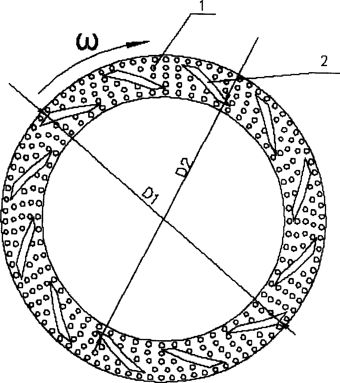
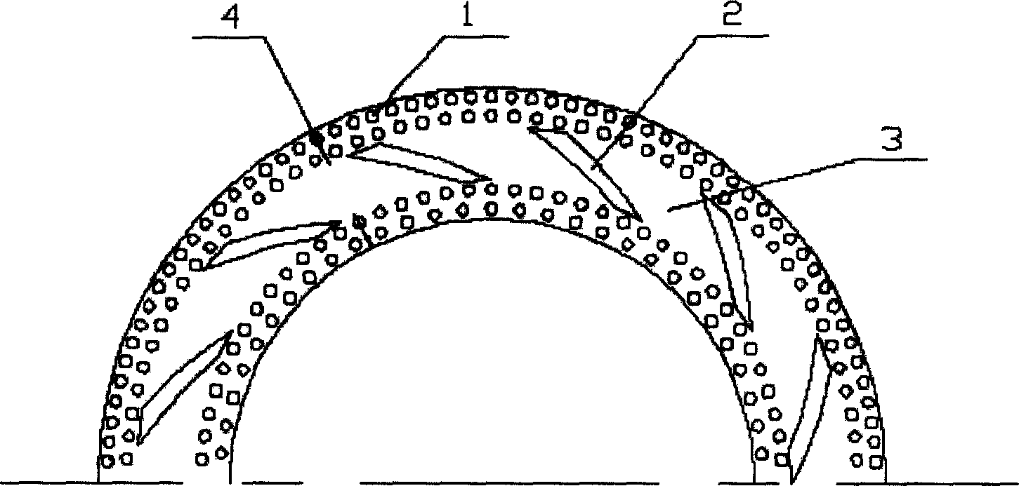
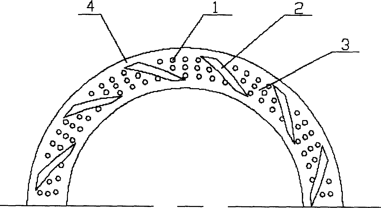
[0020] Embodiment A micro-lubrication chamber (1) evenly distributed in the non-pumping groove area and a pumping groove (2) in the middle of the sealing ring are provided on the dynamic ring of the mechanical seal, see figure 1. The opening of lubricating chamber (1) and pumping groove (2) can be divided into two steps. The first step is to set microscopic lubricating chambers (1) in all areas of the sealing ring. The diameter d of these lubricating chambers (1) is 20-80um, the depth h1 is: 5-20um, and the distance L between the lubricating chambers (1) is 100~300um, such as Figure 7. The second step is to set up a pumping groove (2) in the middle area of ​​the sealing ring. The depth h2 of the pumping groove (2) is slightly greater than the depth h1 of the lubricating chamber (1), so that in the area with the pumping groove (2) , the pumping groove (2) will cover the pre-set microscopic lubricating chamber, thus realizing the staggered combination of the lubricating chamber (1) and the pumping groove (2). The pumping grooves (2) are distributed along the circumferential direction of the sealing ring, the number n of the pumping grooves (2) is 8-30, and the depth h2 is: 8-30um. Since it is set on the sealing moving ring, the inclination direction of the pumping groove (2) is opposite to the rotating direction of the moving ring, such as figure 1 shown. The sealing ring works like this: under working conditions, viscous fluid with a certain pressure enters between the end faces of the sealing dynamic ring or static ring, and due to the existence of the pumping groove (2), the fluid produces a dynamic pressure effect and an upstream pumping effect , the lubricating chamber (1) produces a dynamic pressure effect. In this way, the combination of the two is a significant reflection of the dynamic pressure effect and the upstream pumping effect. The shear flow generated by the upstream pumping effect resists the internal and external pressure difference flow, preventing the sealing medium from leaking outward; the hydrodynamic pressure effect makes the fluid film Axial bearing capacity is generated, which separates the two ends and realizes non-contact, that is, complete fluid lubrication.
[0021] This embodiment is to illustrate the present invention, and its groove shape, distribution position, and lubricating cavity distribution position are not limited, and can be all the situations mentioned in the summary of the invention.

PUM

PropertyMeasurementUnit
Diameter20.0 ~ 80.0µm
Depth5.0 ~ 20.0µm

Description & Claims & Application Information

We can also present the details of the Description, Claims and Application information to help users get a comprehensive understanding of the technical details of the patent, such as background art, summary of invention, brief description of drawings, description of embodiments, and other original content. On the other hand, users can also determine the specific scope of protection of the technology through the list of claims; as well as understand the changes in the life cycle of the technology with the presentation of the patent timeline. Login to view more.

Similar technology patents

Waste incineration boiler of fire grate type circulating fluidized bed and working method thereof

PendingCN111765474ASolve combustion instabilityImprove running stability
Owner:HUANENG CLEAN ENERGY RES INST

Automatic efficient tea planting equipment

PendingCN114586636AImprove running stability
Owner:石门安溪茶业有限责任公司

High-voltage birotor magnetic circuit structure

PendingCN110896256AImprove running stabilityReduce Flux Leakage
Owner:日照东方电机有限公司

Practical mining device

InactiveCN108222827Aprevent tippingImprove running stability
Owner:杨海才

Classification and recommendation of technical efficacy words

  • Extended service life
  • Improve running stability

Fracturing manifold quick connecting device

Owner:YANTAI JEREH PETROLEUM EQUIP & TECH

Modified asphalt composition with creeping characteristic and preparation method thereof

InactiveCN102020859Aavoid rapid agingExtended service life
Owner:ZHEJIANG WOPUMAN HIGH NEW MATERIALS

Double-nozzle-scanning inclined spray type cylinder blank injection moulding device

InactiveCN102145387AImprove running stabilityImprove forming quality
Owner:JIANGSU HAORAN SPRAY FORMING ALLOY

Low-voltage ride-through circuit of doubly-fed wind generator set and control method for low-voltage ride-through circuit

ActiveCN105186559AImprove running stabilityshort transient process
Owner:YANCHENG POWER SUPPLY CO STATE GRID JIANGSU ELECTRIC POWER CO +4

Solar type road traffic light device

InactiveCN106846855AImprove running stabilitysmall temporary space
Owner:XIAMEN CITY WANJIACAN LIGHTING CO LTD

Internal combustion locomotive main generator excitation control device

ActiveCN105553362AImprove device reliabilityImprove running stability
Owner:CRRC DALIAN INST CO LTD
Why Eureka
Try Eureka